
Page 421 - The Mechatronics Handbook
P. 421
0066_frame_C19 Page 43 Wednesday, January 9, 2002 5:17 PM
10 2
9
1
8 Mz
7 4
Fz
3 Fx
6 5 Fy
Mz
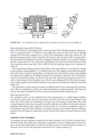
FIGURE 19.39 Force measuring system to determine the tool-related cutting forces in five-axis milling [6].
Measuring Signals Transmitted by Telemetry
Figure 19.39 shows the newly designed force measuring system RCD (rotating cutting force dynamom-
eter). A ring-shaped sensor (1) is fitted in a steep angle taper socket (2) and a base ring (3) allowing
sensing of the three force components F x , F y , and F z at the cutting edge as well as the moment M z . The
physical operating principle of this measuring cell is based on the piezoelectric effect in quartz plates.
The quartz plates incorporated in the sensor are aligned so that the maximum cross-sensitivity between
the force components is 1%. As a result of the rigid design of the sensor, the resonant frequencies of the
force measuring system range from 1200 to 3000 Hz and the measuring ranges cover a maximum of
10 kN [6].
Force-proportional charges produced at the surfaces of the quartz plates are converted into voltages
by four miniature charge amplifiers (7) in hybrid construction. These signals are then filtered by specific
electrical circuitry to prevent aliasing effects, and digitized with 8-bit resolution using a high sampling
rate (pulse-code modulation). The digitized signals are transmitted by a telemetric unit consisting of a
receiver and transmitter module, an antenna at the top of the rotating force measuring system (8), as
well as a fixed antenna (9) on the splash cover of the two-axis milling head (10). The electrical compo-
nents, charge amplifier, and transmitter module are mounted on the circumference of the force measuring
system [6].
The cutting forces and the moment measured are digitized with the force measuring system described
above. They are modulated on an FM carrier and transmitted by the rotating transmitter to the stationary
receiver. The signals transmitted are fed to an external measured-variable conditioning unit.
Measuring Dynamic Forces
Any mechanical system can be considered in the first approximation as a weakly damped oscillator
consisting of a spring and a mass. If a mechanical system has more than one resonant frequency, the
lowest one must be taken into consideration. As long as the test frequency remains below 10% of the
resonant frequency of the reference transducer (used for calibration), the difference between the dynamic
sensitivity obtained from static calibration will be less than 1%. The above considerations assume a
sinusoidal force signal. The static calibration of a reference transducer is also valid for dynamic calibration
purposes if the test frequency is much lower (at least 10 times lower) than the resonant frequency of the
system.
Capacitive Force Transducer
A transducer that uses capacitance variation can be used to measure force. The force is directed onto a
membrane whose elastic deflection is detected by a capacitance variation. A highly sensitive force trans-
ducer can be constructed because the capacitive transducer senses very small deflections accurately. An
electronic circuit converts the capacitance variations into DC-voltage variations [7].
©2002 CRC Press LLC