
Page 415 - The Mechatronics Handbook
P. 415
0066_frame_C19 Page 37 Wednesday, January 9, 2002 5:17 PM
Thin Diaphragm F l F l
P o
P o
Air supply P s
F net P o
F l X
Hydraulic load cell K d K a
F p
A
Pneumatic load cell
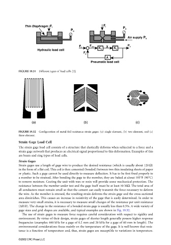
FIGURE 19.31 Different types of load cells [2].
(a) (b) (c)
FIGURE 19.32 Configuration of metal-foil resistance strain gages: (a) single element, (b) two element, and (c)
three element.
Strain Gage Load Cell
The strain gage load cell consists of a structure that elastically deforms when subjected to a force and a
strain gage network that produces an electrical signal proportional to this deformation. Examples of this
are beam and ring types of load cells.
Strain Gages
Strain gages use a length of gage wire to produce the desired resistance (which is usually about 120 Ω)
in the form of a flat coil. This coil is then cemented (bonded) between two thin insulating sheets of paper
or plastic. Such a gage cannot be used directly to measure deflection. It has to be first fixed properly to
a member to be strained. After bonding the gage to the member, they are baked at about 195°F (90°C)
to remove moisture. Coating the unit with wax or resin will provide some mechanical protection. The
resistance between the member under test and the gage itself must be at least 50 MΩ. The total area of
all conductors must remain small so that the cement can easily transmit the force necessary to deform
the wire. As the member is stressed, the resulting strain deforms the strain gage and the cross-sectional
area diminishes. This causes an increase in resistivity of the gage that is easily determined. In order to
measure very small strains, it is necessary to measure small changes of the resistance per unit resistance
(∆R/R). The change in the resistance of a bonded strain gage is usually less than 0.5%. A wide variety of
gage sizes and grid shapes are available, and typical examples are shown in Fig. 19.32.
The use of strain gages to measure force requires careful consideration with respect to rigidity and
environment. By virtue of their design, strain gages of shorter length generally possess higher response
frequencies (examples: 660 kHz for a gage of 0.2 mm and 20 kHz for a gage of 60 mm in length). The
environmental considerations focus mainly on the temperature of the gage. It is well known that resis-
tance is a function of temperature and, thus, strain gages are susceptible to variations in temperature.
©2002 CRC Press LLC