
Page 429 - The Mechatronics Handbook
P. 429
0066_Frame_C19 Page 51 Wednesday, January 9, 2002 5:27 PM
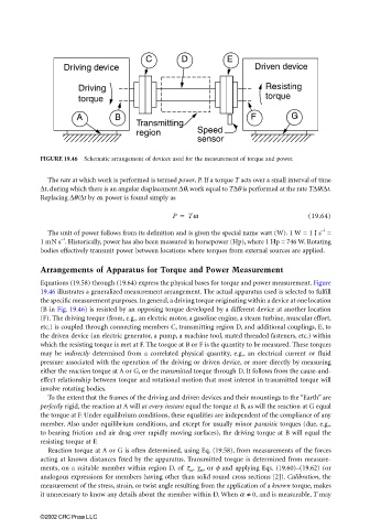
C D E
Driving device Driven device
Driving Resisting
torque torque
A B F G
Transmitting
region Speed
sensor
FIGURE 19.46 Schematic arrangement of devices used for the measurement of torque and power.
The rate at which work is performed is termed power, P. If a torque T acts over a small interval of time
∆t, during which there is an angular displacement ∆θ, work equal to T∆θ is performed at the rate T∆θ/∆t.
Replacing ∆θ/∆t by ω, power is found simply as
P = Tw (19.64)
The unit of power follows from its definition and is given the special name watt (W). 1 W = 1 J s =
–1
–1
1 mN s . Historically, power has also been measured in horsepower (Hp), where 1 Hp = 746 W. Rotating
bodies effectively transmit power between locations where torques from external sources are applied.
Arrangements of Apparatus for Torque and Power Measurement
Equations (19.58) through (19.64) express the physical bases for torque and power measurement. Figure
19.46 illustrates a generalized measurement arrangement. The actual apparatus used is selected to fulfill
the specific measurement purposes. In general, a driving torque originating within a device at one location
(B in Fig. 19.46) is resisted by an opposing torque developed by a different device at another location
(F). The driving torque (from, e.g., an electric motor, a gasoline engine, a steam turbine, muscular effort,
etc.) is coupled through connecting members C, transmitting region D, and additional couplings, E, to
the driven device (an electric generator, a pump, a machine tool, mated threaded fasteners, etc.) within
which the resisting torque is met at F. The torque at B or F is the quantity to be measured. These torques
may be indirectly determined from a correlated physical quantity, e.g., an electrical current or fluid
pressure associated with the operation of the driving or driven device, or more directly by measuring
either the reaction torque at A or G, or the transmitted torque through D. It follows from the cause-and-
effect relationship between torque and rotational motion that most interest in transmitted torque will
involve rotating bodies.
To the extent that the frames of the driving and driven devices and their mountings to the “Earth” are
perfectly rigid, the reaction at A will at every instant equal the torque at B, as will the reaction at G equal
the torque at F. Under equilibrium conditions, these equalities are independent of the compliance of any
member. Also under equilibrium conditions, and except for usually minor parasitic torques (due, e.g.,
to bearing friction and air drag over rapidly moving surfaces), the driving torque at B will equal the
resisting torque at F.
Reaction torque at A or G is often determined, using Eq. (19.58), from measurements of the forces
acting at known distances fixed by the apparatus. Transmitted torque is determined from measure-
ments, on a suitable member within region D, of τ m , γ m , or φ and applying Eqs. (19.60)–(19.62) (or
analogous expressions for members having other than solid round cross sections [2]). Calibration, the
measurement of the stress, strain, or twist angle resulting from the application of a known torque, makes
it unnecessary to know any details about the member within D. When α ≠ 0, and is measurable, T may
©2002 CRC Press LLC