
Page 431 - The Mechatronics Handbook
P. 431
0066_Frame_C19 Page 53 Wednesday, January 9, 2002 5:27 PM
Toothed
Brushes To external wheels
Strain gauges circuit
Torsion
Insulator section
Slip Rings
Pickups
(a) (b)
Helical Coil
knurls or bobbin Domain wall Polarized ring
grooves
Excitation Magnetic
and sense flux line Field sensor
windings
(c) (d)
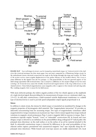
FIGURE 19.47 Four techniques in present use for measuring transmitted torque. (a) Torsional strain in the shaft
alters the electrical resistance for four strain gages (two not seen) connected in a Wheatstone bridge circuit. In
the embodiment shown, electrical connections are made to the bridge through slip rings and brushes. (b) Twist
of the torsion section causes angular displacement of the surface features on the toothed wheels. This creates a
phase difference in the signals from the two pickups. (c) The permeabilities of the two grooved regions of the
shaft change oppositely with torsional stress. This is sensed as a difference in the output voltages of the two sense
windings. (d) Torsional stress causes the initially circumferential magnetizations in the ring (solid arrows) to tilt
(dashed arrows). These helical magnetizations cause magnetic poles to appear at the domain wall and ring ends.
The resulting magnetic field is sensed by the field sensor.
With more elaborate pickups, the relative angular position of the two wheels appears as the amplitude
of a single electrical signal, thus providing for the measurement of torque even on a stationary shaft (e.g.,
[13–15]). In still other constructions, a shaft-mounted variable displacement transformer or a related
type of electrical device is used to provide speed independent output signals proportional to φ.
Stress
In addition to elastic strain, the stresses by which torque is transmitted are manifested by changes in the
magnetic properties of ferromagnetic shaft materials. This “magnetoelastic interaction” [8] provides an
inherently noncontacting basis for measuring torque. Two types of magnetoelastic (sometimes called
magnetostrictive) torque transducers are in present use: Type 1 derive output signals from torque-induced
variations in magnetic circuit permeances; Type 2 create a magnetic field in response to torque. Type 1
transducers typically employ “branch,” “cross,” or “solenoidal” constructions [9]. In branch and cross
designs, torque is detected as an imbalance in the permeabilities along orthogonal 45° helical paths (the
principal stress directions) on the shaft surface or on the surface of an ad hoc material attached to the
shaft. In solenoidal constructions torque is detected by differences in the axial permeabilities of two
adjacent surface regions, preendowed with symmetrical magnetic “easy” axes (typically along the 45°
principal stress directions). While branch and cross-type sensors are readily miniaturized [10], local
©2002 CRC Press LLC