
Page 432 - The Mechatronics Handbook
P. 432
0066_Frame_C19 Page 54 Wednesday, January 9, 2002 5:27 PM
variations in magnetic properties of typical shaft surfaces limit their accuracy. Solenoidal designs, illus-
trated in Fig. 19.47(c), avoid this pitfall by effectively averaging these variations. Type 2 transducers are
generally constructed with a ring of magnetoelastically active material rigidly attached to the shaft. The
ring is magnetized during manufacture of the transducer, usually with each axial half polarized in an
opposite circumferential direction as indicated by the solid arrows in Fig. 19.47(d) [11]. When torque is
applied, the magnetizations tilt into helical directions (dashed arrows), causing magnetic poles to develop
at the central domain wall and (of opposite polarity) at the ring end faces. Torque is determined from
the output signal of one or more magnetic field sensors (e.g., Hall effect, magnetoresistive, or flux gate
devices) mounted so as to sense the intensity and polarity of the magnetic field that arises in the space
near the ring.
Torque Transducer Construction, Operation, and Application
Although a torque sensing region can be created directly on a desired shaft, it is more usual to install a
preassembled modular torque transducer into the driveline. Transducers of this type are available with
capacities from 0.001 to 200,000 Nm. Operating principle descriptions and detailed installation and
operating instructions can be found in the catalogs and literature of the various manufacturers [12–20].
Tradenames often identify a specific type of transducers; for example, Torquemeters [13] refers to a family
of noncontact strain gage models; Torkducer®[18] identifies a line of Type 1 magnetoelastic transducers;
Torqstar TM [12] identifies a line of Type 2 magnetoelastic transducers; Torquetronic [16] is a class of
transducers using wrap-around twist angle sensors; and TorXimitor TM [20] identifies optoelectronic-
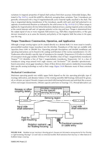
based, noncontact, strain gage transducers. Many of these devices show generic similarities transcending
their specific sensing technology as well as their range. Figure 19.48 illustrates many of these common
features.
Mechanical Considerations
Maximum operating speeds vary widely; upper limits depend on the size, operating principle, type of
bearings, lubrication, and dynamic balance of the rotating assembly. Ball bearings, lubricated by grease,
oil, or oil mist, are typical. Parasitic torques associated with bearing lubricants and seals limit the accuracy
of low-end torque measurements. (Minute capacity units have no bearings [15].) Forced lubrication can
Keyway or other Ancillary components
coupling detail for the specific
sensing technology Bearing *
Sensing region
Input side Load side
shaft extension shaft extension
Housing
Feet for
rigid mounting
Electrical connector
Rotation restraint or cable entry
for floating housing
FIGURE 19.48 Modular torque transducer showing generic features and alternative arrangements for free floating
or rigid mounting. Bearings* are used only on rotational models. Shaft extensions have keyways or other features to
facilitate torque coupling.
©2002 CRC Press LLC