
Page 437 - The Mechatronics Handbook
P. 437
0066_Frame_C19 Page 59 Wednesday, January 9, 2002 5:27 PM
Cooling water Stator
passages windings
Trunnion
bearings Stator
G
Toothed
rotor
Input Load
coupling
S cell
Calibration Pedestal
weights
Base
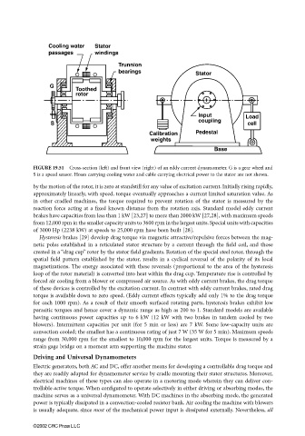
FIGURE 19.51 Cross-section (left) and front view (right) of an eddy current dynamometer. G is a gear wheel and
S is a speed sensor. Hoses carrying cooling water and cable carrying electrical power to the stator are not shown.
by the motion of the rotor, it is zero at standstill for any value of excitation current. Initially rising rapidly,
approximately linearly, with speed, torque eventually approaches a current limited saturation value. As
in other cradled machines, the torque required to prevent rotation of the stator is measured by the
reaction force acting at a fixed known distance from the rotation axis. Standard model eddy current
brakes have capacities from less than 1 kW [23,27] to more than 2000 kW [27,28], with maximum speeds
from 12,000 rpm in the smaller capacity units to 3600 rpm in the largest units. Special units with capacities
of 3000 Hp (2238 kW) at speeds to 25,000 rpm have been built [28].
Hysteresis brakes [29] develop drag torque via magnetic attractive/repulsive forces between the mag-
netic poles established in a reticulated stator structure by a current through the field coil, and those
created in a “drag cup” rotor by the stator field gradients. Rotation of the special steel rotor, through the
spatial field pattern established by the stator, results in a cyclical reversal of the polarity of its local
magnetizations. The energy associated with these reversals (proportional to the area of the hysteresis
loop of the rotor material) is converted into heat within the drag cup. Temperature rise is controlled by
forced air cooling from a blower or compressed air source. As with eddy current brakes, the drag torque
of these devices is controlled by the excitation current. In contrast with eddy current brakes, rated drag
torque is available down to zero speed. (Eddy current effects typically add only 1% to the drag torque
for each 1000 rpm). As a result of their smooth surfaced rotating parts, hysteresis brakes exhibit low
parasitic torques and hence cover a dynamic range as high as 200 to 1. Standard models are available
having continuous power capacities up to 6 kW (12 kW with two brakes in tandem cooled by two
blowers). Intermittent capacities per unit (for 5 min or less) are 7 kW. Some low-capacity units are
convection cooled; the smallest has a continuous rating of just 7 W (35 W for 5 min). Maximum speeds
range from 30,000 rpm for the smallest to 10,000 rpm for the largest units. Torque is measured by a
strain gage bridge on a moment arm supporting the machine stator.
Driving and Universal Dynamometers
Electric generators, both AC and DC, offer another means for developing a controllable drag torque and
they are readily adapted for dynamometer service by cradle mounting their stator structures. Moreover,
electrical machines of these types can also operate in a motoring mode wherein they can deliver con-
trollable active torque. When configured to operate selectively in either driving or absorbing modes, the
machine serves as a universal dynamometer. With DC machines in the absorbing mode, the generated
power is typically dissipated in a convection-cooled resistor bank. Air cooling the machine with blowers
is usually adequate, since most of the mechanical power input is dissipated externally. Nevertheless, all
©2002 CRC Press LLC