
Page 441 - The Mechatronics Handbook
P. 441
0066_Frame_C19 Page 63 Wednesday, January 9, 2002 5:27 PM
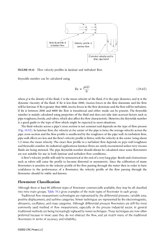
Velocity profile in Velocity profile in
turbulent flow
laminar flow
Distorted velocity profile
after pipe bend
FIGURE 19.52 Flow velocity profiles in laminar and turbulent flow.
Reynolds number can be calculated using
Re = rvD (19.65)
----------
h
v
where ρ is the density of the fluid, is the mean velocity of the fluid, D is the pipe diameter, and η is the
dynamic viscosity of the fluid. If Re is less than 2000, viscous forces in the flow dominate and the flow
will be laminar. If Re is greater than 4000, inertia forces in the flow dominate and the flow will be turbulent.
If Re is between 2000 and 4000 the flow is transitional and either mode can be present. The Reynolds
number is mainly calculated using properties of the fluid and does not take into account factors such as
pipe roughness, bends, and valves, which also affect the flow characteristic. However, the Reynolds number
is a good guide to the type of flow which might be expected in most situations.
The fluid velocity across a pipe’s cross section is not constant and depends on the type of flow present
(Fig. 19.52). In laminar flow, the velocity at the center of the pipe is twice the average velocity across the
pipe cross-section and the flow profile is unaffected by the roughness of the pipe wall. In turbulent flow,
pipe wall effects are less and the flow’s velocity profile is flatter, with the velocity at the center being about
1.2 times the mean velocity. The exact flow profile in a turbulent flow depends on pipe wall roughness
and Reynolds number. In industrial applications laminar flows are rarely encountered unless very viscous
fluids are being metered. The pipe Reynolds number should always be calculated since some flowmeters
are not suitable for use in both laminar and turbulent flow conditions.
A flow’s velocity profile will only be symmetrical at the end of a very long pipe. Bends and obstructions
such as valves will cause the profile to become distorted or asymmetric. Since the calibration of many
flowmeters is sensitive to the velocity profile of the flow passing through the meter then in order to have
confidence in the performance of a flowmeter, the velocity profile of the flow passing through the
flowmeter should be stable and known.
Flowmeter Classification
Although there at least 80 different types of flowmeter commercially available, they may be all classified
into nine main groups. Table 19.3 gives examples of the main types of flowmeter in each group.
Traditional flow measurement technologies are represented by the differential pressure, variable area,
positive displacement, and turbine categories. Newer techniques are represented by the electromagnetic,
ultrasonic, oscillatory, and mass categories. Although differential pressure flowmeters are still the most
commonly used method of flow measurement, especially in the process industrial sector, in general
traditional methods are being increasingly replaced by newer techniques. These techniques are now often
preferred because in most cases they do not obstruct the flow, and yet match many of the traditional
flowmeters in terms of accuracy and reliability.
©2002 CRC Press LLC