
Page 446 - The Mechatronics Handbook
P. 446
0066_Frame_C19 Page 68 Wednesday, January 9, 2002 5:27 PM
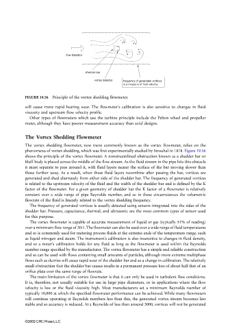
flow direction
shedder bar
vortex detector frequency of generated vortices
is a measure of fluid velocity
FIGURE 19.56 Principle of the vortex shedding flowmeter.
will cause more rapid bearing wear. The flowmeter’s calibration is also sensitive to changes in fluid
viscosity and upstream flow velocity profile.
Other types of flowmeters which use the turbine principle include the Pelton wheel and propeller
meter, although they have poorer measurement accuracy than axial designs.
The Vortex Shedding Flowmeter
The vortex shedding flowmeter, now more commonly known as the vortex flowmeter, relies on the
phenomena of vortex shedding, which was first experimentally studied by Strouhal in 1878. Figure 19.56
shows the principle of the vortex flowmeter. A nonstreamlined obstruction known as a shedder bar or
bluff body is placed across the middle of the flow stream. As the fluid stream in the pipe hits this obstacle
it must separate to pass around it, with fluid layers nearer the surface of the bar moving slower than
those further away. As a result, when these fluid layers recombine after passing the bar, vortices are
generated and shed alternately from either side of the shedder bar. The frequency of generated vortices
is related to the upstream velocity of the fluid and the width of the shedder bar and is defined by the K
factor of the flowmeter. For a given geometry of shedder bar the K factor of a flowmeter is relatively
constant over a wide range of pipe Reynolds number, and so in these circumstances the volumetric
flowrate of the fluid is linearly related to the vortex shedding frequency.
The frequency of generated vortices is usually detected using sensors integrated into the sides of the
shedder bar. Pressure, capacitance, thermal, and ultrasonic are the most common types of sensor used
for this purpose.
The vortex flowmeter is capable of accurate measurement of liquid or gas (typically ±1% of reading)
over a minimum flow range of 30:1. The flowmeter can also be used over a wide range of fluid temperatures
and so is commonly used for metering process fluids at the extreme ends of the temperature range, such
as liquid nitrogen and steam. The instrument’s calibration is also insensitive to changes in fluid density,
and so a meter’s calibration holds for any fluid as long as the flowmeter is used within the Reynolds
number range specified by the manufacturer. The vortex flowmeter has a simple and reliable construction
and so can be used with flows containing small amounts of particles, although more extreme multiphase
flows such as slurries will cause rapid wear of the shedder bar and so a change in calibration. The relatively
small obstruction that the shedder bar causes results in a permanent pressure loss of about half that of an
orifice plate over the same range of flowrate.
The main limitation of the vortex flowmeter is that it can only be used in turbulent flow conditions.
It is, therefore, not usually suitable for use in large pipe diameters, or in applications where the flow
velocity is low or the fluid viscosity high. Most manufacturers set a minimum Reynolds number of
typically 10,000 at which the specified flowmeter performance can be achieved. While many flowmeters
will continue operating at Reynolds numbers less than this, the generated vortex stream becomes less
stable and so accuracy is reduced. At a Reynolds of less than around 3000, vortices will not be generated
©2002 CRC Press LLC