
Page 445 - The Mechatronics Handbook
P. 445
0066_Frame_C19 Page 67 Wednesday, January 9, 2002 5:27 PM
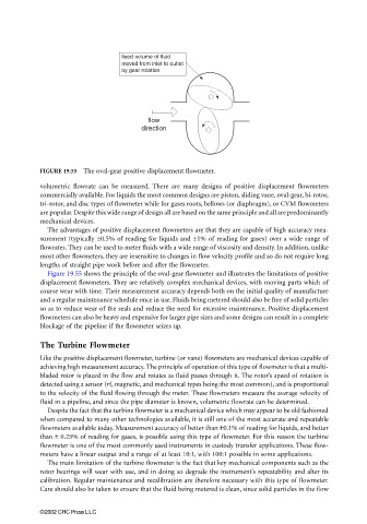
fixed volume of fluid
moved from inlet to outlet
by gear rotation
flow
direction
FIGURE 19.55 The oval-gear positive displacement flowmeter.
volumetric flowrate can be measured. There are many designs of positive displacement flowmeters
commercially available. For liquids the most common designs are piston, sliding vane, oval-gear, bi-rotor,
tri-rotor, and disc types of flowmeter while for gases roots, bellows (or diaphragm), or CVM flowmeters
are popular. Despite this wide range of design all are based on the same principle and all are predominantly
mechanical devices.
The advantages of positive displacement flowmeters are that they are capable of high accuracy mea-
surement (typically ±0.5% of reading for liquids and ±1% of reading for gases) over a wide range of
flowrates. They can be used to meter fluids with a wide range of viscosity and density. In addition, unlike
most other flowmeters, they are insensitive to changes in flow velocity profile and so do not require long
lengths of straight pipe work before and after the flowmeter.
Figure 19.55 shows the principle of the oval-gear flowmeter and illustrates the limitations of positive
displacement flowmeters. They are relatively complex mechanical devices, with moving parts which of
course wear with time. Their measurement accuracy depends both on the initial quality of manufacture
and a regular maintenance schedule once in use. Fluids being metered should also be free of solid particles
so as to reduce wear of the seals and reduce the need for excessive maintenance. Positive displacement
flowmeters can also be heavy and expensive for larger pipe sizes and some designs can result in a complete
blockage of the pipeline if the flowmeter seizes up.
The Turbine Flowmeter
Like the positive displacement flowmeter, turbine (or vane) flowmeters are mechanical devices capable of
achieving high measurement accuracy. The principle of operation of this type of flowmeter is that a multi-
bladed rotor is placed in the flow and rotates as fluid passes through it. The rotor’s speed of rotation is
detected using a sensor (rf, magnetic, and mechanical types being the most common), and is proportional
to the velocity of the fluid flowing through the meter. These flowmeters measure the average velocity of
fluid in a pipeline, and since the pipe diameter is known, volumetric flowrate can be determined.
Despite the fact that the turbine flowmeter is a mechanical device which may appear to be old fashioned
when compared to many other technologies available, it is still one of the most accurate and repeatable
flowmeters available today. Measurement accuracy of better than ±0.1% of reading for liquids, and better
than ± 0.25% of reading for gases, is possible using this type of flowmeter. For this reason the turbine
flowmeter is one of the most commonly used instruments in custody transfer applications. These flow-
meters have a linear output and a range of at least 10:1, with 100:1 possible in some applications.
The main limitation of the turbine flowmeter is the fact that key mechanical components such as the
rotor bearings will wear with use, and in doing so degrade the instrument’s repeatability and alter its
calibration. Regular maintenance and recalibration are therefore necessary with this type of flowmeter.
Care should also be taken to ensure that the fluid being metered is clean, since solid particles in the flow
©2002 CRC Press LLC