
Page 444 - The Mechatronics Handbook
P. 444
0066_Frame_C19 Page 66 Wednesday, January 9, 2002 5:27 PM
calibrated
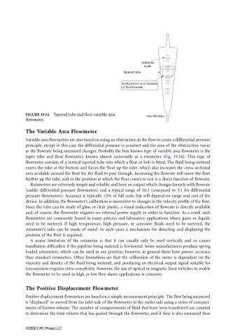
scale
tapered tube
float position is a measure
of fluid flowrate
FIGURE 19.54 Tapered tube and float variable area
flow direction
flowmeter.
The Variable Area Flowmeter
Variable area flowmeters are also based on using an obstruction in the flow to create a differential pressure
principle, except in this case the differential pressure is constant and the area of the obstruction varies
as the flowrate being measured changes. Probably the best known type of variable area flowmeter is the
taper tube and float flowmeter, known almost universally as a rotameter (Fig. 19.54). This type of
flowmeter consists of a vertical tapered tube into which a float or bob is fitted. The fluid being metered
enters the tube at the bottom and forces the float up the tube, which also increases the cross-sectional
area available around the float for the fluid to pass through. Increasing the flowrate will move the float
further up the tube, and so the position at which the float comes to rest is a direct function of flowrate.
Rotameters are extremely simple and reliable, and have an output which changes linearly with flowrate
(unlike differential pressure flowmeters) and a typical range of 10:1 (compared to 3:1 for differential
pressure flowmeters). Accuracy is typically ±2% of full scale, but will depend on range and cost of the
device. In addition, the flowmeter’s calibration is insensitive to changes in the velocity profile of the flow.
Since the tube can be made of glass or clear plastic, a visual indication of flowrate is directly available
and, of course, the flowmeter requires no external power supply in order to function. As a result such
flowmeters are commonly found in many process and laboratory applications where gases or liquids
need to be metered. If high temperature, high pressure, or corrosive fluids need to be metered, the
rotameter’s tube can be made of metal. In such cases a mechanism for detecting and displaying the
position of the float is required.
A major limitation of the rotameter is that it can usually only be used vertically and so causes
installation difficulties if the pipeline being metered is horizontal. Some manufacturers produce spring
loaded rotameters, which can be used in any position; however, in general these have poorer accuracy
than standard rotameters. Other limitations are that the calibration of the meter is dependent on the
viscosity and density of the fluid being metered, and producing an electrical output signal suitable for
transmission requires extra complexity. However, the use of optical or magnetic limit switches to enable
the flowmeter to be used in high or low flow alarm applications is common.
The Positive Displacement Flowmeter
Positive displacement flowmeters are based on a simple measurement principle. The flow being measured
is “displaced” or moved from the inlet side of the flowmeter to the outlet side using a series of compart-
ments of known volume. The number of compartments of fluid that have been transferred are counted
to determine the total volume that has passed through the flowmeter, and if time is also measured then
©2002 CRC Press LLC