
Page 582 - The Mechatronics Handbook
P. 582
0066_Frame_C20 Page 52 Wednesday, January 9, 2002 5:49 PM
Z (3)
6
5
Y (2)
4
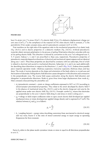
FIGURE 20.81 X (1)
2
here S is strain (m), T is stress (N/m ), E is electric field (V/m), D is dielectric displacement (charge per
T
2
2
E
unit area (C/m )), s is the compliance of the material (m /N) when electric field is constant, ε is the
permittivity (F/m) under constant stress, and d is piezoelectric constant (m/V or C/N).
First members on the right side of the equations refer to the mechanical properties of an elastic body
(Eq. (20.31)) and to electric properties of a dielectric medium (Eq. (20.32)). Artificial piezoelectric
materials obtain remnant polarization in the process of poling. Polarization direction coincides with one
of the poling electric fields. This direction is referred by convention to the axis Z of orthogonal axes X,
Y, Z system. Indexes 1, 2, and 3 are prescribed to these axes, respectively. Piezoelectric properties of
piezoelectric materials depend on directions of electrical and mechanical inputs/outputs and are identical
along axes 1 and 2. Thus these properties are described by constants with two subscripts, first of which
is related to electrical and second to mechanical direction. Subscripts 4, 5, and 6 are used additionally
for describing shear distortions in respect to the directions 1, 2, and 3 (Fig. 20.81). Indexes show possible
piezo materials operation mode—thickness expansion, transverse expansion, thickness shear, and face
shear. The mode of motion depends on the shape and orientation of the body relative to crystal axes and
the location of electrodes. Poling electric field direction causes elongation in this direction and contraction
in the perpendicular ones. The reverse field causes contraction along the electric field direction and
elongation in perpendicular directions. Mode d 33 gives three times larger displacement than mode d 31 .
Main constants characterizing the piezoeffect are:
• d ij (piezoelectric constant)—strain or charge coefficients expressed in M/V or C/N (according to
sensor/actuator piezomaterial properties). They relate to the strain developed by electric field E
in the absence of mechanical stress (Eq. (20.31)), and to the electric charge per unit area by the
applied stress under zero electric field (Eq. (20.32)). Example: symbol d 31 means that electrodes
are perpendicular to the axis 3 (electric field along it) and stress or strain is along axis 1.
• g ij —voltage or field output coefficients relate to open circuit electric field developed per applied
mechanical stress or strain developed per applied charge density and is expressed in V m/N. The
relation between d ij and g ij is as follows:
g ij = d ij (20.33)
-----
ε T
• k ij (coupling factors)—energy ratios describing conversion from mechanical to electrical energy
2
and vice versa. Factor k is the ratio of stored converted energy to input energy at operating
frequencies far from resonant.
2 d 2
k = --------- (20.34)
s ε
E T
Factor k p refers to the plane mode operation (strain or stress is equal in all directions perpendicular
to axis 3).
©2002 CRC Press LLC