
Page 577 - The Mechatronics Handbook
P. 577
0066_Frame_C20 Page 47 Wednesday, January 9, 2002 5:49 PM
V
DC
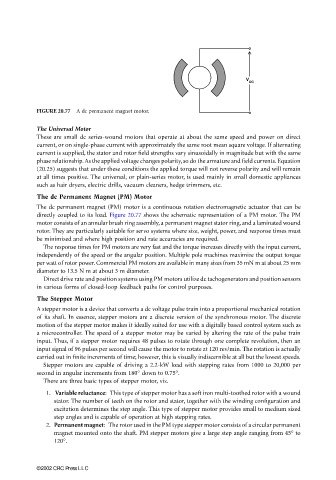
FIGURE 20.77 A dc permanent magnet motor.
The Universal Motor
These are small dc series-wound motors that operate at about the same speed and power on direct
current, or on single-phase current with approximately the same root mean square voltage. If alternating
current is supplied, the stator and rotor field strengths vary sinusoidally in magnitude but with the same
phase relationship. As the applied voltage changes polarity, so do the armature and field currents. Equation
(20.25) suggests that under these conditions the applied torque will not reverse polarity and will remain
at all times positive. The universal, or plain-series motor, is used mainly in small domestic appliances
such as hair dryers, electric drills, vacuum cleaners, hedge trimmers, etc.
The dc Permanent Magnet (PM) Motor
The dc permanent magnet (PM) motor is a continuous rotation electromagnetic actuator that can be
directly coupled to its load. Figure 20.77 shows the schematic representation of a PM motor. The PM
motor consists of an annular brush ring assembly, a permanent magnet stator ring, and a laminated wound
rotor. They are particularly suitable for servo systems where size, weight, power, and response times must
be minimized and where high position and rate accuracies are required.
The response times for PM motors are very fast and the torque increases directly with the input current,
independently of the speed or the angular position. Multiple pole machines maximize the output torque
per watt of rotor power. Commercial PM motors are available in many sizes from 35 mN m at about 25 mm
diameter to 13.5 N m at about 3 m diameter.
Direct drive rate and position systems using PM motors utilize dc tachogenerators and position sensors
in various forms of closed-loop feedback paths for control purposes.
The Stepper Motor
A stepper motor is a device that converts a dc voltage pulse train into a proportional mechanical rotation
of its shaft. In essence, stepper motors are a discrete version of the synchronous motor. The discrete
motion of the stepper motor makes it ideally suited for use with a digitally based control system such as
a microcontroller. The speed of a stepper motor may be varied by altering the rate of the pulse train
input. Thus, if a stepper motor requires 48 pulses to rotate through one complete revolution, then an
input signal of 96 pulses per second will cause the motor to rotate at 120 rev/min. The rotation is actually
carried out in finite increments of time; however, this is visually indiscernible at all but the lowest speeds.
Stepper motors are capable of driving a 2.2-kW load with stepping rates from 1000 to 20,000 per
second in angular increments from 180° down to 0.75°.
There are three basic types of stepper motor, viz.
1. Variable reluctance: This type of stepper motor has a soft iron multi-toothed rotor with a wound
stator. The number of teeth on the rotor and stator, together with the winding configuration and
excitation determines the step angle. This type of stepper motor provides small to medium sized
step angles and is capable of operation at high stepping rates.
2. Permanent magnet: The rotor used in the PM type stepper motor consists of a circular permanent
magnet mounted onto the shaft. PM stepper motors give a large step angle ranging from 45° to
120°.
©2002 CRC Press LLC