
Page 573 - The Mechatronics Handbook
P. 573
0066_Frame_C20 Page 43 Wednesday, January 9, 2002 5:49 PM
R 1
Y 0
B 0
-
Rotor
+
B 1
Y 1
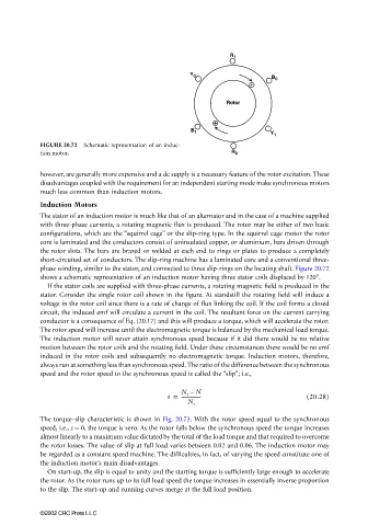
FIGURE 20.72 Schematic representation of an induc-
tion motor. R 0
however, are generally more expensive and a dc supply is a necessary feature of the rotor excitation. These
disadvantages coupled with the requirement for an independent starting mode make synchronous motors
much less common than induction motors.
Induction Motors
The stator of an induction motor is much like that of an alternator and in the case of a machine supplied
with three-phase currents, a rotating magnetic flux is produced. The rotor may be either of two basic
configurations, which are the “squirrel cage” or the slip-ring type. In the squirrel cage motor the rotor
core is laminated and the conductors consist of uninsulated copper, or aluminium, bars driven through
the rotor slots. The bars are brazed or welded at each end to rings or plates to produce a completely
short-circuited set of conductors. The slip-ring machine has a laminated core and a conventional three-
phase winding, similar to the stator, and connected to three slip-rings on the locating shaft. Figure 20.72
shows a schematic representation of an induction motor having three stator coils displaced by 120°.
If the stator coils are supplied with three-phase currents, a rotating magnetic field is produced in the
stator. Consider the single rotor coil shown in the figure. At standstill the rotating field will induce a
voltage in the rotor coil since there is a rate of change of flux linking the coil. If the coil forms a closed
circuit, the induced emf will circulate a current in the coil. The resultant force on the current carrying
conductor is a consequence of Eq. (20.17) and this will produce a torque, which will accelerate the rotor.
The rotor speed will increase until the electromagnetic torque is balanced by the mechanical load torque.
The induction motor will never attain synchronous speed because if it did there would be no relative
motion between the rotor coils and the rotating field. Under these circumstances there would be no emf
induced in the rotor coils and subsequently no electromagnetic torque. Induction motors, therefore,
always run at something less than synchronous speed. The ratio of the difference between the synchronous
speed and the rotor speed to the synchronous speed is called the “slip”; i.e.,
N s – N
s = ---------------- (20.28)
N s
The torque–slip characteristic is shown in Fig. 20.73. With the rotor speed equal to the synchronous
speed, i.e., s = 0, the torque is zero. As the rotor falls below the synchronous speed the torque increases
almost linearly to a maximum value dictated by the total of the load torque and that required to overcome
the rotor losses. The value of slip at full load varies between 0.02 and 0.06. The induction motor may
be regarded as a constant speed machine. The difficulties, in fact, of varying the speed constitute one of
the induction motor’s main disadvantages.
On start-up, the slip is equal to unity and the starting torque is sufficiently large enough to accelerate
the rotor. As the rotor runs up to its full load speed the torque increases in essentially inverse proportion
to the slip. The start-up and running curves merge at the full load position.
©2002 CRC Press LLC