
Page 570 - The Mechatronics Handbook
P. 570
0066_Frame_C20 Page 40 Wednesday, January 9, 2002 5:49 PM
I a
I f
R a
Supply
V
E M
FIGURE 20.66 Speed control by flux reduction: series-wound motor.
I a
I f
R a
Supply
V
E M
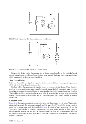
FIGURE 20.67 Speed control by varying the armature voltage.
The potential divider carries the same current as the motor, and this limits this method of speed
control to small machines. Additionally much of the input energy is dissipated in the variable resistance,
which consequently renders the system inefficient.
Ward Leonard Drive
In this case the variable dc voltage for the speed controlled motor is obtained from a separate dc generator,
which is in itself driven by an induction motor.
The field coil for the dc generator is supplied from a center-zero potential divider. When the wiper
arm is in the center position, the speed controlled motor is at a standstill. By moving the wiper arm away
from the center position the speed of the motor is increased in either clockwise or anti-clockwise direction.
The Ward Leonard drive is smooth and accurate in either direction and also provides for very responsive
braking. The complexity, however, makes it a very expensive system, and it is only used in high quality
applications.
Chopper Control
Figure 20.68 shows a thyristor circuit connected in series with the armature of a dc motor. The thyristor
circuit is triggered such that it operates essentially as a high speed ON/OFF switch. The output waveform
across the armature terminals is depicted in Fig. 20.69. The ratio of time on to time off, i.e., the
“mark/space ratio,” can be varied with the result that the average voltage supplied to the armature is
effectively varied between zero and fully on. The frequency of the signal may be up to about 3 kHz and
the timing circuit is quite complex. Speed control of dc motors using thyristors, however, is effective and
relatively inexpensive.
©2002 CRC Press LLC