
Page 574 - The Mechatronics Handbook
P. 574
0066_Frame_C20 Page 44 Wednesday, January 9, 2002 5:49 PM
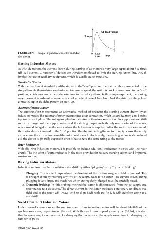
Full-load Torque
Torque
FIGURE 20.73 Torque–slip characteristic for an induc- 0 0.02-
tion motor. 0.06 Slip
Starting Induction Motors
As with dc motors, the current drawn during starting of ac motors is very large, up to about five times
full load current. A number of devices are therefore employed to limit the starting current but they all
involve the use of auxiliary equipment, which is usually quite expensive.
Star-Delta Starter
With the machine at standstill and the starter in the “start” position, the stator coils are connected in the
star pattern. As the machine accelerates up to running speed, the switch is quickly moved over to the “run”
position, which reconnects the stator windings in the delta pattern. By this simple expedient, the starting
supply current is reduced to about one third of what it would have been had the stator windings been
connected up in the delta pattern on start-up.
Autotransformer Starter
The autotransformer represents an alternative method of reducing the starting current drawn by an
induction motor. The autotransformer incorporates a star connection, which is supplied from a mid-point
tapping on each phase. The voltage supplied to the stator is, therefore, one half of the supply voltage. With
such an arrangement the supply current and the starting torque are both only one quarter of the values,
which would be applied to the motor when the full voltage is supplied. After the motor has accelerated,
the starter device is moved to the “run” position thereby connecting the motor directly across the supply
and opening the star-connection of the autotransformer. Unfortunately, the starting torque is also reduced
and the device is generally expensive since it has to have the same rating as the motor.
Rotor Resistance
With slip-ring induction motors, it is possible to include additional resistance in series with the rotor
circuit. The inclusion of extra resistance in the rotor provides for reduced starting current and improved
starting torque.
Braking Induction Motors
Induction motors may be brought to a standstill by either “plugging” or by “dynamic braking.”
1. Plugging: This is a technique where the direction of the rotating magnetic field is reversed. This
is brought about by reversing any two of the supply leads to the stator. The current drawn during
plugging is very large, and machines which are regularly plugged must be specially rated.
2. Dynamic braking: In this braking method the stator is disconnected from the ac supply and
reconnected to a dc source. The direct current in the stator produces a stationary unidirectional
field and as the rotor will always tend to align itself with the field, it will therefore come to a
standstill.
Speed Control of Induction Motors
Under normal circumstances, the running speed of an induction motor will be about 94–98% of the
synchronous speed, depending on the load. With the synchronous speed given by Eq. (20.26), it is clear
that the speed may be varied either by changing the frequency of the supply current, or by changing the
number of poles.
©2002 CRC Press LLC