
Page 575 - The Mechatronics Handbook
P. 575
0066_Frame_C20 Page 45 Wednesday, January 9, 2002 5:49 PM
Change of Supply Current Frequency
Solid state variable-frequency drives first began to appear in 1968. They were originally applied to the
control of synchronous ac motors in the synthetic fiber industry and rapidly gained acceptance in that
particular market. In more recent times they have been used in applications to pumping, synchronized
press lines, conveyor lines, and to a lesser extent in the machine-tool industry as spindle drives. Modern
ac variable-frequency motors are available in power ratings ranging from 1 to 750 kW and with speed
ranges from 10/1 to 100/1.
The synchronous and squirrel cage induction motors are the types most commonly used in conjunction
with solid-state, adjustable frequency inverter systems. In operation the motor runs at, or near, the
synchronous speed determined by the input current frequency. The torque available at low speed,
however, is decreased and the motor may have to be somewhat oversized to ensure adequate performance
at the lower speeds. The most advanced systems incorporate a digital tachogenerator to supply a corrective
feedback signal which is compared against a reference frequency. This gives a speed regulation of about
3%. Consequently, the ac variable-frequency drive is generally used only for moderate to high power
velocity control applications, where a wide range of speed is not required. The comparative simplicity
of the ac induction motor is usually sacrificed to the complexity and cost of the control electronics.
Change of Number of Poles
By bringing out the ends of the stator coils to a specially designed switch it becomes possible to change
an induction motor from one pole configuration to another. To obtain three different pole numbers, and
hence three different speeds, a fairly complex switching device would be required.
Changing the number of poles gives a discrete change in motor speed with little variation in speed
over the switched range. For many applications, however, two discrete speeds are all that is required and
changing the number of poles is a simple and effective method af achieving this.
Changing the Rotor Resistance
For slip-ring induction motors additional resistance can be coupled in series with the rotor circuit. It
has already been stated that this is a common enough method used to limit the starting current of such
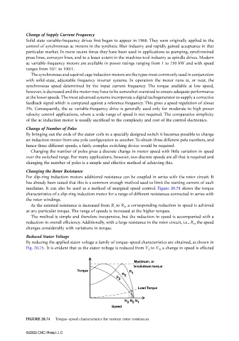
machines. It can also be used as a method of marginal speed control. Figure 20.74 shows the torque
characteristics of a slip-ring induction motor for a range of different resistances connected in series with
the rotor windings.
As the external resistance is increased from R 1 to R 3 , a corresponding reduction in speed is achieved
at any particular torque. The range of speeds is increased at the higher torques.
The method is simple and therefore inexpensive, but the reduction in speed is accompanied with a
reduction in overall efficiency. Additionally, with a large resistance in the rotor circuit, i.e., R 3 , the speed
changes considerably with variations in torque.
Reduced Stator Voltage
By reducing the applied stator voltage a family of torque–speed characteristics are obtained, as shown in
Fig. 20.75. It is evident that as the stator voltage is reduced from V 1 to V 3 , a change in speed is effected
Maximum, or
breakdown torque
Torque R
R 2 1
R
3
Load Torque
N N N
3 2 1
Speed
FIGURE 20.74 Torque–speed characteristics for various rotor resistances.
©2002 CRC Press LLC