
Page 579 - The Mechatronics Handbook
P. 579
0066_Frame_C20 Page 49 Thursday, January 10, 2002 10:36 AM
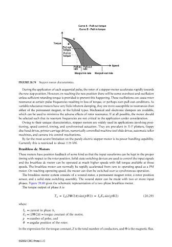
Curve A - Pull-out torque
Curve B - Pull-in torque
A
Torque B
Pull-out
torque
Pull-in
torque
Speed
Pull-in Pull-out
rate rate
Maxpull-in rate Maxpull-out rate
FIGURE 20.79 Stepper motor characteristics.
During the application of each sequential pulse, the rotor of a stepper motor accelerates rapidly towards
the new step position. However, on reaching the new position there will be some overshoot and oscillation
unless sufficient retarding torque is provided to prevent this happening. These oscillations can cause rotor
resonance at certain pulse frequencies resulting in loss of torque, or perhaps even pull-out conditions. As
variable reluctance motors have very little inherent damping, they are more susceptible to resonances than
either of the permanent magnet, or the hybrid types. Mechanical and electronic dampers are available,
which can be used to minimize the adverse effects of rotor resonance. If at all possible, the motor should
be selected such that its resonant frequencies are not critical to the application under consideration.
Owing to their unique characteristics, stepper motors are widely used in applications involving posi-
tioning, speed control, timing, and synchronized actuation. They are prevalent in X-Y plotters, floppy
disc head drives, printer carriage drives, numerically controlled machine tool slide drives, automatic teller
machines, and camera iris control mechanisms.
By far the most severe limitation on the purely electric stepper motor is its power handling capability.
Currently this is restricted to about 2.25 kW.
Brushless dc Motors
These motors have position feedback of some kind so that the input waveforms can be kept in the proper
timing with respect to the rotor position. Solid-state switching devices are used to control the input signals
and the brushless dc motor can be operated at much higher speeds with full torque available at those
speeds. The brushless motor can normally be rapidly accelerated from zero to operating speed as a PM
motor. On reaching operating speed, the motor can then be switched over to synchronous operation.
The brushless motor system consists of a wound stator, a permanent magnet rotor, a rotor position
sensor, and a solid state switching assembly. The wound stator can be made with two or more input
phases. Figure 20.80 gives the schematic representation of a two-phase brushless motor.
The torque output of phase A is
(
T A = I A ZΦ/2π)sin ( pθ/2) = I A K T sin ( pθ/2) (20.29)
where
Ι Α = current in phase A,
K T = (ZΦ/2π) = torque constant of the motor,
p = number of poles, and
θ = angular position of the rotor.
In the expression for the torque constant, Z is the total number of conductors, and Φ is the magnetic flux.
©2002 CRC Press LLC