
Page 572 - The Mechatronics Handbook
P. 572
0066_Frame_C20 Page 42 Wednesday, January 9, 2002 5:49 PM
R 1
Y 0 B 0
V
DC
B 1 Y 1
R 0
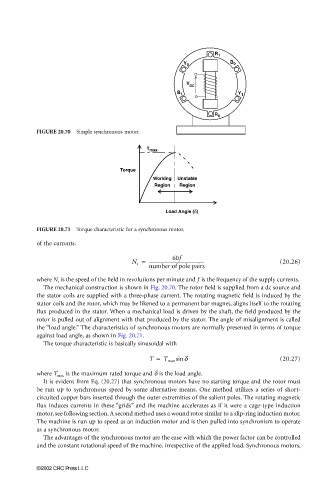
FIGURE 20.70 Simple synchronous motor.
T max
Torque
Working Unstable
Region Region
Load Angle (δ)
FIGURE 20.71 Torque characteristic for a synchronous motor.
of the currents.
60f
N s = -------------------------------------------------- (20.26)
number of pole pairs
where N s is the speed of the field in revolutions per minute and f is the frequency of the supply currents.
The mechanical construction is shown in Fig. 20.70. The rotor field is supplied from a dc source and
the stator coils are supplied with a three-phase current. The rotating magnetic field is induced by the
stator coils and the rotor, which may be likened to a permanent bar magnet, aligns itself to the rotating
flux produced in the stator. When a mechanical load is driven by the shaft, the field produced by the
rotor is pulled out of alignment with that produced by the stator. The angle of misalignment is called
the “load angle.” The characteristics of synchronous motors are normally presented in terms of torque
against load angle, as shown in Fig. 20.71.
The torque characteristic is basically sinusoidal with
T = T max sin δ (20.27)
where T max is the maximum rated torque and δ is the load angle.
It is evident from Eq. (20.27) that synchronous motors have no starting torque and the rotor must
be run up to synchronous speed by some alternative means. One method utilizes a series of short-
circuited copper bars inserted through the outer extremities of the salient poles. The rotating magnetic
flux induces currents in these “grids” and the machine accelerates as if it were a cage-type induction
motor, see following section. A second method uses a wound rotor similar to a slip-ring induction motor.
The machine is run up to speed as an induction motor and is then pulled into synchronism to operate
as a synchronous motor.
The advantages of the synchronous motor are the ease with which the power factor can be controlled
and the constant rotational speed of the machine, irrespective of the applied load. Synchronous motors,
©2002 CRC Press LLC