
Page 711 - The Mechatronics Handbook
P. 711
0066_Frame_C23 Page 19 Wednesday, January 9, 2002 1:53 PM
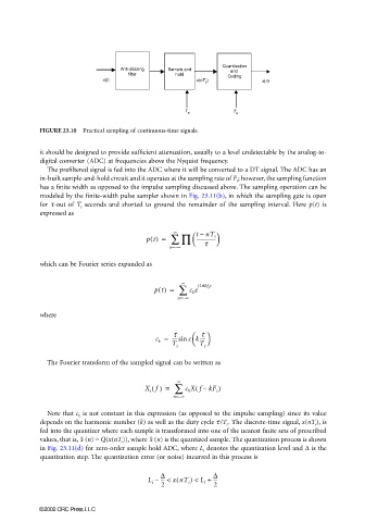
FIGURE 23.10 Practical sampling of continuous-time signals.
it should be designed to provide sufficient attenuation, usually to a level undetectable by the analog-to-
digital converter (ADC) at frequencies above the Nyquist frequency.
The prefiltered signal is fed into the ADC where it will be converted to a DT signal. The ADC has an
in-built sample-and-hold circuit and it operates at the sampling rate of F s ; however, the sampling function
has a finite width as opposed to the impulse sampling discussed above. The sampling operation can be
modeled by the finite-width pulse sampler shown in Fig. 23.11(b), in which the sampling gate is open
for τ-out of T s seconds and shorted to ground the remainder of the sampling interval. Here p(t) is
expressed as
∞
–
pt() = ∑ ∏ tnT s
----------------
τ
n=∞
–
which can be Fourier series expanded as
∞ j2πkf t
pt() = ∑ c k e s
n=∞
–
where
τ τ
c k = -----sin ck-----
T s T s
The Fourier transform of the sampled signal can be written as
∞
(
X s f() = ∑ c k Xf kF s )
–
n=∞
–
Note that c k is not constant in this expression (as opposed to the impulse sampling) since its value
depends on the harmonic number (k) as well as the duty cycle τ /T s . The discrete-time signal, x(nT s ), is
fed into the quantizer where each sample is transformed into one of the nearest finite sets of prescribed
values, that is, (n) = Q(x(nT s )), where (n) is the quantized sample. The quantization process is shownx ˆ x ˆ
in Fig. 23.11(d) for zero-order sample hold ADC, where L i denotes the quantization level and ∆ is the
quantization step. The quantization error (or noise) incurred in this process is
∆ ∆
(
L i – --- < xnT s ) < L i + ---
2 2
©2002 CRC Press LLC