
Page 105 - Theory and Design of Air Cushion Craft
P. 105
Air cushion wave-making drag 89
1.0
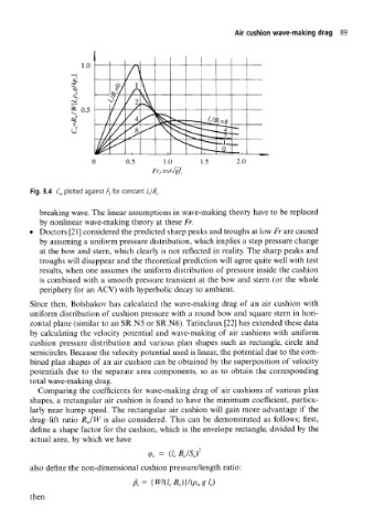
Fr, =v/-JgT c
Fig. 3.4 C w plotted against />, for constant Z C/5 C.
breaking wave. The linear assumptions in wave-making theory have to be replaced
by nonlinear wave-making theory at these Fr.
• Doctors [21] considered the predicted sharp peaks and troughs at low Fr are caused
by assuming a uniform pressure distribution, which implies a step pressure change
at the bow and stern, which clearly is not reflected in reality. The sharp peaks and
troughs will disappear and the theoretical prediction will agree quite well with test
results, when one assumes the uniform distribution of pressure inside the cushion
is combined with a smooth pressure transient at the bow and stern (or the whole
periphery for an ACV) with hyperbolic decay to ambient.
Since then, Bolshakov has calculated the wave-making drag of an air cushion with
uniform distribution of cushion pressure with a round bow and square stern in hori-
zontal plane (similar to an SR.N5 or SR.N6). Tatinclaux [22] has extended these data
by calculating the velocity potential and wave-making of air cushions with uniform
cushion pressure distribution and various plan shapes such as rectangle, circle and
semicircles. Because the velocity potential used is linear, the potential due to the com-
bined plan shapes of an air cushion can be obtained by the superposition of velocity
potentials due to the separate area components, so as to obtain the corresponding
total wave-making drag.
Comparing the coefficients for wave-making drag of air cushions of various plan
shapes, a rectangular air cushion is found to have the minimum coefficient, particu-
larly near hump speed. The rectangular air cushion will gain more advantage if the
drag-lift ratio RJW is also considered. This can be demonstrated as follows; first,
define a shape factor for the cushion, which is the envelope rectangle, divided by the
actual area, by which we have
= B c/S cf
9t (/ c
also define the non-dimensional cushion pressure/length ratio:
p c=
then