
Page 173 - Theory and Design of Air Cushion Craft
P. 173
156 Stability
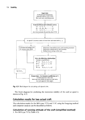
Input data
Craft principal dimensions
Sidewall offsets, LCG, VCG
Bow and stern seal dimensions
Generate thrust and resistance curves
V,, V 2, V 3,
V i= V n
R T = R Jt, /? T2, /? T3 .V Tn
T= T t, T 2, T 3 T n
also trim moments M R and M R about VCG
At speed V, assume a series of inner bow and stern drafts t hi, t s,
Calculate air leakage area Determine sidewall buoyancy and restoring moments
for various inner drafts Determine cushion forces and moments
Define forces acting on the seals
Solve the following relationships:
(iterate to equilibrium)
[t b,,t ho, r,,, t sa, ]
W=f L Pc
t
Q=f [tu, t bo, si, t so, ]
Pc
PC =f [Q]
[t bi,t bo, t si, t so, p c]
M=f w
Output data - for dynamic equilibrium at V,
Cushion pressure, flow rate,
inner and outer drafts at craft bow and stern,
true and apparent trim angles
Fig. 4.21 Block diagram for calculating craft dynamic trim.
The block diagram for predicting the transverse stability of the craft at speed is
shown in Fig. 4.22.
Calculation results for two actual craft
The calculation results for the SES types 717A and 717C using the foregoing method
and computer analysis can be described as follows.
Calculation of running attitude of the craft (simplified method)
1. For SES type 717A (Table 4.5):