
Page 337 - Thomson, William Tyrrell-Theory of Vibration with Applications-Taylor _ Francis (2010)
P. 337
324 Introduction to the Finite Element Method Chap. 10
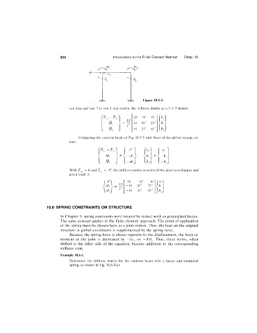
Figure 10.5-5.
can also add row 3 to row 1 and rewrite the stiffness matrix as a 3 X 3 matrix:
24 6/ 61
M, 6/ 8/' 21" <
6/ 21" SI" 6, I
V -)
Comparing the external loads of Fig. 10.5-5 with those of the global system, we
have
/ \ /
+ F'lv "i U
M, >= < > - < -6
- ^ 2 / -e
With ^ 2 ^ = 0 and F, ^ = 5^, the stiffness matrix in terms of the given coordinates and
given loads is
■ 24 -6 1 -6 1
E/
-6 1 SI" 21"
■'^2 ) -6 1 21" SI"
10.6 SPRING CONSTRAINTS ON STRUCTURE
In Chapter 9, spring constraints were treated by virtual work as generalized forces.
The same concept applies in the finite element approach. The point of application
of the spring must be chosen here as a joint station. Thus, the load on the original
structure in global coordinates is supplemented by the spring force.
Because the spring force is always opposite to the displacement, the force or
moment at the joint is decreased by -/cr, -KO^. Thus, these terms, when
shifted to the other side of the equation, become additions to the corresponding
stiffness term.
Example 10.6-1
Determine the stiffness matrix for the uniform beam with a linear and rotational
spring, as shown in Fig. 10.6-l(a).