
Page 130 - Thermal Hydraulics Aspects of Liquid Metal Cooled Nuclear Reactors
P. 130
Design of experimental liquid-metal facilities 103
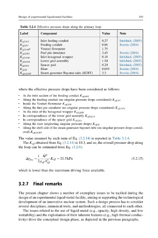
Table 3.2.4 Effective pressure drops along the primary loop
Label Component Value Note
K eff,IFC Inlet feeding conduit 0.27 Idelchick (2005)
K eff,FC Feeding conduit 0.06 Rozzia (2014)
K eff,FM e Venturi flowmeter 1.75
Fuel pin simulator 2.45 Rozzia (2014)
K eff,FPS
Inlet hexagonal wrapper 0.18 Idelchick (2005)
K eff,IHW
Lower grid assembly 1.54 Idelchick (2005)
K eff,LGA
Spacer grid 0.24 Idelchick (2005)
K eff,SGr
Riser 0.019 Rozzia (2014)
K eff,R
Steam generator Bayonet tube (SGBT) 3.3 Rozzia (2014)
K eff,SGBT
where the effective pressure drops have been considered as follows:
l
At the inlet section of the feeding conduit K eff,IFC
l
Along the feeding conduit (no singular pressure drops considered) K eff,FC
l
Inside the Venturi flowmeter K eff,FM
l
Along the fuel pin simulator (no singular pressure drops considered) K eff,FPS
l
At the inlet of the hexagonal wrapper K eff,IHW
l
In correspondence of the lower grid assembly K eff,LGA
l
In correspondence of the spacer grid K eff,SGr
l
Along the riser (neglecting singular pressure drops) K eff,R
Along the shell side of the steam generator bayonet tube (no singular pressure drops consid-
l
ered) K eff,SGBT
The value assumed by each term of Eq. (3.2.14) is reported in Table 3.2.4.
The K eff obtained from Eq. (3.2.14) is 10.3, and so, the overall pressure drop along
the loop can be estimated from Eq. (3.2.9):
1 M _ 2
Δp fric ¼ 2 K eff ¼ 21:5kPa (3.2.15)
2ρ A
eff eff
which is lower than the maximum driving force available.
3.2.7 Final remarks
The present chapter shows a number of exemplary issues to be tackled during the
design of an experimental liquid-metal facility, aiming at supporting the technological
development of an innovative nuclear system. Such a design process has to consider
several disciplines, numerical tools, and methodologies, all connected to each other.
The issues related to the use of liquid metal (e.g., opacity, high density, and low
wettability) and the exploitation of their inherent features (e.g., high thermal conduc-
tivity) drive the conceptual design phase, as depicted in the previous paragraphs.