
Page 129 - Thermal Hydraulics Aspects of Liquid Metal Cooled Nuclear Reactors
P. 129
102 Thermal Hydraulics Aspects of Liquid Metal Cooled Nuclear Reactors
The effective flow area and density have been set equal to the fuel pin simulator flow
area and the LBE average density along the stream, respectively.
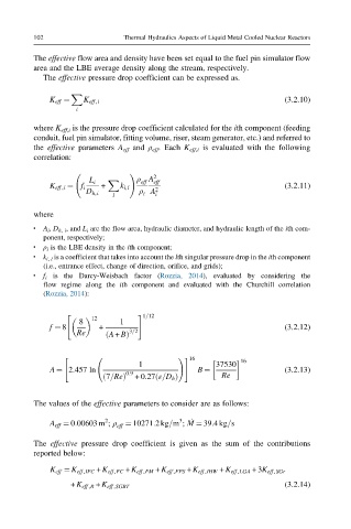
The effective pressure drop coefficient can be expressed as.
X
K eff ¼ K eff,i (3.2.10)
i
where K eff,i is the pressure drop coefficient calculated for the ith component (feeding
conduit, fuel pin simulator, fitting volume, riser, steam generator, etc.) and referred to
the effective parameters A eff and ρ eff . Each K eff,i is evaluated with the following
correlation:
! 2
ρ A
L i X eff eff
K eff,i ¼ f i + k i,l 2 (3.2.11)
D h,i ρ A i
i
l
where
l A i , D h, i , and L i are the flow area, hydraulic diameter, and hydraulic length of the ith com-
ponent, respectively;
ρ i is the LBE density in the ith component;
l
k i, l is a coefficient that takes into account the lth singular pressure drop in the ith component
l
(i.e., entrance effect, change of direction, orifice, and grids);
f i is the Darcy-Weisbach factor (Rozzia, 2014), evaluated by considering the
l
flow regime along the ith component and evaluated with the Churchill correlation
(Rozzia, 2014):
1=12
" #
8 1
12
f ¼ 8 + (3.2.12)
Re ð A + BÞ 3=2
" !# 16 16
1 37530
A ¼ 2:457 ln B ¼ (3.2.13)
0:9
ð
ð 7=ReÞ +0:27 ε=D h Þ Re
The values of the effective parameters to consider are as follows:
_
2
A eff ¼ 0:00603 m ; ρ eff ¼ 10271:2kg=m ; M ¼ 39:4kg=s
3
The effective pressure drop coefficient is given as the sum of the contributions
reported below:
K eff ¼ K eff,IFC + K eff,FC + K eff,FM + K eff,FPS + K eff ,IHW + K eff ,LGA +3K eff,SGr
+ K eff ,R + K eff ,SGBT (3.2.14)