
Page 124 - Thermal Hydraulics Aspects of Liquid Metal Cooled Nuclear Reactors
P. 124
Design of experimental liquid-metal facilities 97
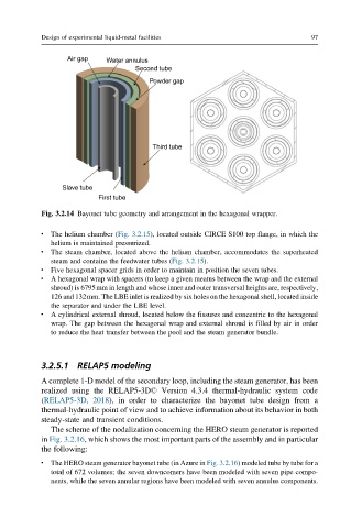
Air gap Water annulus
Second tube
Powder gap
Third tube
Slave tube
First tube
Fig. 3.2.14 Bayonet tube geometry and arrangement in the hexagonal wrapper.
l The helium chamber (Fig. 3.2.15), located outside CIRCE S100 top flange, in which the
helium is maintained pressurized.
l The steam chamber, located above the helium chamber, accommodates the superheated
steam and contains the feedwater tubes (Fig. 3.2.15).
l Five hexagonal spacer grids in order to maintain in position the seven tubes.
l A hexagonal wrap with spacers (to keep a given meatus between the wrap and the external
shroud) is 6795mm in length and whose inner and outer transversal heights are, respectively,
126 and 132mm. The LBE inlet is realized by six holes on the hexagonal shell, located inside
the separator and under the LBE level.
l A cylindrical external shroud, located below the fissures and concentric to the hexagonal
wrap. The gap between the hexagonal wrap and external shroud is filled by air in order
to reduce the heat transfer between the pool and the steam generator bundle.
3.2.5.1 RELAP5 modeling
A complete 1-D model of the secondary loop, including the steam generator, has been
realized using the RELAP5-3D© Version 4.3.4 thermal-hydraulic system code
(RELAP5-3D, 2018), in order to characterize the bayonet tube design from a
thermal-hydraulic point of view and to achieve information about its behavior in both
steady-state and transient conditions.
The scheme of the nodalization concerning the HERO steam generator is reported
in Fig. 3.2.16, which shows the most important parts of the assembly and in particular
the following:
l The HERO steam generator bayonet tube (in Azure in Fig. 3.2.16) modeled tube by tube for a
total of 672 volumes; the seven downcomers have been modeled with seven pipe compo-
nents, while the seven annular regions have been modeled with seven annulus components.