
Page 119 - Thermal Hydraulics Aspects of Liquid Metal Cooled Nuclear Reactors
P. 119
92 Thermal Hydraulics Aspects of Liquid Metal Cooled Nuclear Reactors
Fig. 3.2.8 Sketch of the mesh developed in the fluid region (left) and in the solid domain (right).
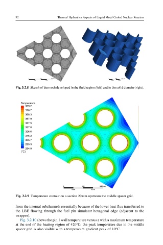
Fig. 3.2.9 Temperature contour on a section 20mm upstream the middle spacer grid.
from the internal subchannels essentially because of the lower heat flux transferred to
the LBE flowing through the fuel pin simulator hexagonal edge (adjacent to the
wrapper).
Fig. 3.2.10 shows the pin 1 wall temperature versus z with a maximum temperature
at the end of the heating region of 420°C; the peak temperature due to the middle
spacer grid is also visible with a temperature gradient peak of 10°C.