
Page 121 - Thermal Hydraulics Aspects of Liquid Metal Cooled Nuclear Reactors
P. 121
94 Thermal Hydraulics Aspects of Liquid Metal Cooled Nuclear Reactors
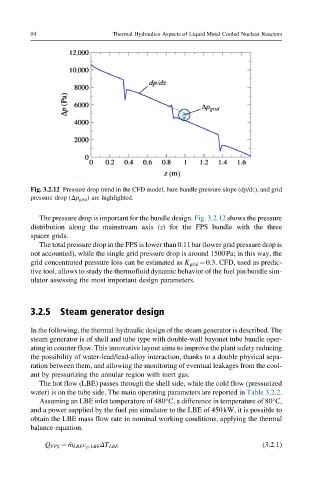
Fig. 3.2.12 Pressure drop trend in the CFD model, bare bundle pressure slope (dp/dz), and grid
pressure drop (Δp grid ) are highlighted.
The pressure drop is important for the bundle design. Fig. 3.2.12 shows the pressure
distribution along the mainstream axis (z) for the FPS bundle with the three
spacer grids.
The total pressure drop in the FPS is lower than 0.11bar (lower grid pressure drop is
not accounted), while the single grid pressure drop is around 1500Pa; in this way, the
grid concentrated pressure loss can be estimated as K grid ¼0.3. CFD, used as predic-
tive tool, allows to study the thermofluid dynamic behavior of the fuel pin bundle sim-
ulator assessing the most important design parameters.
3.2.5 Steam generator design
In the following, the thermal-hydraulic design of the steam generator is described. The
steam generator is of shell and tube type with double-wall bayonet tube bundle oper-
ating in counter flow. This innovative layout aims to improve the plant safety reducing
the possibility of water-lead/lead-alloy interaction, thanks to a double physical sepa-
ration between them, and allowing the monitoring of eventual leakages from the cool-
ant by pressurizing the annular region with inert gas.
The hot flow (LBE) passes through the shell side, while the cold flow (pressurized
water) is on the tube side. The main operating parameters are reported in Table 3.2.2.
Assuming an LBE inlet temperature of 480°C, a difference in temperature of 80°C,
and a power supplied by the fuel pin simulator to the LBE of 450kW, it is possible to
obtain the LBE mass flow rate in nominal working conditions, applying the thermal
balance equation.
Q FPS ¼ _ m LBE c p,LBE ΔT LBE (3.2.1)