
Page 118 - Thermal Hydraulics Aspects of Liquid Metal Cooled Nuclear Reactors
P. 118
Design of experimental liquid-metal facilities 91
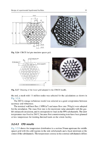
Fig. 3.2.6 CIRCE fuel pin simulator spacer grid.
14,76 Triangular pitch
Nº 36 holes 10,4 R3,4
Nº 37 holes Ø5,5
100
6
Fig. 3.2.7 Drawing of the lower grid adopted in the CIRCE bundle.
the end, a mesh with 11 million nodes was selected for the calculations as shown in
Fig. 3.2.8.
The SST k-omega turbulence model was selected as a good compromise between
accuracy and robustness.
2
The nominal wall heat flux (1MW/m ) and mass flow rate (70kg/s) were adopted
for the simulation. The mass flow rate is the maximum value attainable with the gas-
lift-enhanced circulation, and it corresponds to 1m/s in the FPS subchannels. The inlet
temperature was fixed to 286°C, because first commissioning tests have been planned
at low temperature for limiting thermal loads on the whole facility.
3.2.4.3 CFD results
Fig. 3.2.9 shows the temperature distribution in a section 20mm upstream the middle
spacer grid with the cold regions in the side subchannels and a local minimum at the
center of the subchannels. The temperature contour in the external subchannels differs