
Page 122 - Thermal Hydraulics Aspects of Liquid Metal Cooled Nuclear Reactors
P. 122
Design of experimental liquid-metal facilities 95
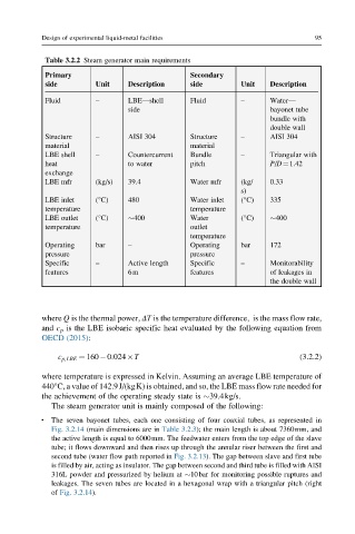
Table 3.2.2 Steam generator main requirements
Primary Secondary
side Unit Description side Unit Description
Fluid – LBE—shell Fluid – Water—
side bayonet tube
bundle with
double wall
Structure – AISI 304 Structure – AISI 304
material material
LBE shell – Countercurrent Bundle – Triangular with
heat to water pitch P/D¼1.42
exchange
LBE mfr (kg/s) 39.4 Water mfr (kg/ 0.33
s)
LBE inlet (°C) 480 Water inlet (°C) 335
temperature temperature
LBE outlet (°C) 400 Water (°C) 400
temperature outlet
temperature
Operating bar – Operating bar 172
pressure pressure
Specific – Active length Specific – Monitorability
features 6m features of leakages in
the double wall
where Q is the thermal power, ΔT is the temperature difference, is the mass flow rate,
and c p is the LBE isobaric specific heat evaluated by the following equation from
OECD (2015):
c p,LBE ¼ 160 0:024 T (3.2.2)
where temperature is expressed in Kelvin. Assuming an average LBE temperature of
440°C, a value of 142.9J/(kgK) is obtained, and so, the LBE mass flow rate needed for
the achievement of the operating steady state is 39.4kg/s.
The steam generator unit is mainly composed of the following:
The seven bayonet tubes, each one consisting of four coaxial tubes, as represented in
l
Fig. 3.2.14 (main dimensions are in Table 3.2.3); the main length is about 7360mm, and
the active length is equal to 6000mm. The feedwater enters from the top edge of the slave
tube; it flows downward and then rises up through the annular riser between the first and
second tube (water flow path reported in Fig. 3.2.13). The gap between slave and first tube
is filled by air, acting as insulator. The gap between second and third tube is filled with AISI
316L powder and pressurized by helium at 10bar for monitoring possible ruptures and
leakages. The seven tubes are located in a hexagonal wrap with a triangular pitch (right
of Fig. 3.2.14).