
Page 116 - Thermal Hydraulics Aspects of Liquid Metal Cooled Nuclear Reactors
P. 116
Design of experimental liquid-metal facilities 89
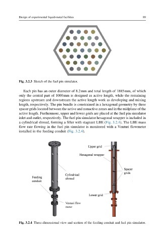
Fig. 3.2.3 Sketch of the fuel pin simulator.
Each pin has an outer diameter of 8.2mm and total length of 1885mm, of which
only the central part of 1000mm is designed as active length, while the remaining
regions upstream and downstream the active length work as developing and mixing
length, respectively. The pin bundle is constrained in a hexagonal geometry by three
spacer grids located between the active and nonactive zones and in the midplane of the
active length. Furthermore, upper and lower grids are placed at the fuel pin simulator
inlet and outlet, respectively. The fuel pin simulator hexagonal wrapper is included in
a cylindrical shroud, forming a filler with stagnant LBE (Fig. 3.2.4). The LBE mass
flow rate flowing in the fuel pin simulator is monitored with a Venturi flowmeter
installed in the feeding conduit (Fig. 3.2.4).
Fig. 3.2.4 Three-dimensional view and section of the feeding conduit and fuel pin simulator.