
Page 222 - Thermal Hydraulics Aspects of Liquid Metal Cooled Nuclear Reactors
P. 222
Subchannel analysis for LMR 193
D
P
S ij
Z Y
X
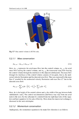
Fig. 5.7 One control volume in SCTH code.
5.2.1.1 Mass conservation
_ m K,out _ m K,in + _ m K,int ¼ 0 (5.4)
Here, m k, in represents the axial mass flow into the control volume, m k, out the axial
mass flow leaving the control volume, and m k, int the transversal mass flow leaving
the control volume through the interfaces to the adjacent subchannels. The mass flow
through the interfaces of the control volume consists of two parts, that is, the undi-
rected velocity fluctuation and the directed cross flow. They are expressed by the mass
flux G resulted by the undirected velocity fluctuation and mass flux G* due to the
0
directed cross flow:
X X ∗
0
_ m K,int ¼ s ij Δz G G 0 ji + s ij Δz G ij (5.5)
ij
J J
Here, Δz is the height of the control volume and s ij the width of the gap between both
subchannels i and j. The control rod dimensions and fluxes may vary from one axial
node to the next, but the subscript K is omitted from the right-hand side of this equa-
tion and later equations for the sake of brevity. More about the transversal exchange is
discussed in the next subchapter.
5.2.1.2 Momentum conservation
Analogously, the momentum equation in the main flow direction is as follows: