
Page 220 - Thermal Hydraulics Aspects of Liquid Metal Cooled Nuclear Reactors
P. 220
Subchannel analysis for LMR 191
codes and treat the entire reactor core as one or a few flow channels. This approach is
widely applied to the thermal-hydraulic analysis of the entire cooling system of the
nuclear power plant, where the reactor core is only one part of the analysis domain.
This approach focuses on the dynamic behavior of the entire complex cooling system
and provides only average values of thermal-hydraulic parameters in reactor core or
fuel assembly, which usually are not sufficient for the design purpose.
In contrast to the STH approach, CFD focuses on finer-scale phenomena where
turbulent flow and heat transfer around geometric features like pins, wire wraps,
and assembly cans are modeled explicitly. Due to the high requirement on the storage
need and computing time, application of this approach is mostly limited to a section of
one fuel assembly or even a section of one subchannel. Application of the CFD
approach to the final design purpose is still limited at the present stage.
The SCTH analysis method is the most widely applied approach in the thermal-
hydraulic design of fuel assembly and/or reactor core. Each fuel assembly is divided
into a large number of individual flow channels, the so-called subchannels. With this
approach, the thermal-hydraulic parameters averaged over each subchannel can be
obtained, and the hot subchannel or the hot fuel pin can be identified.
5.2 SCTH analysis
The main strategy of the SCTH analysis is to calculate the average values of the
required thermal-hydraulic parameters in each subchannel. Therefore, the division
or the definition of subchannels plays an important role and might vary from case
to case, according to the requirements of the analysis. The conventional way to divide
subchannels is to define their boundary. In general, the boundary of one subchannel
consists of solid surface, for example, the fuel rod surface or the box surface and the
narrow gaps between the solid surfaces. Similar to the hexagonal fuel assembly shown
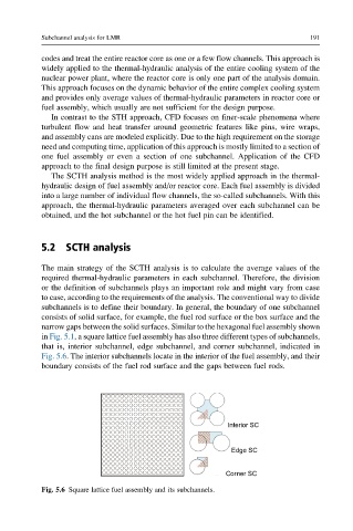
in Fig. 5.1, a square lattice fuel assembly has also three different types of subchannels,
that is, interior subchannel, edge subchannel, and corner subchannel, indicated in
Fig. 5.6. The interior subchannels locate in the interior of the fuel assembly, and their
boundary consists of the fuel rod surface and the gaps between fuel rods.
Interior SC
Edge SC
Corner SC
Fig. 5.6 Square lattice fuel assembly and its subchannels.