
Page 216 - Thermal Hydraulics Aspects of Liquid Metal Cooled Nuclear Reactors
P. 216
Subchannel analysis for LMR 187
D
P
Interior SC
Edge SC
Corner SC
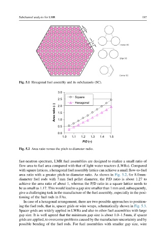
Fig. 5.1 Hexagonal fuel assembly and its subchannels (SC).
3.0
Square
2.5
Hexagonal
Area ratio (–) 1.5
2.0
1.0
0.5
0.0
1.0 1.1 1.2 1.3 1.4 1.5
P/D (–)
Fig. 5.2 Area ratio versus the pitch-to-diameter radio.
fast-neutron spectrum, LMR fuel assemblies are designed to realize a small ratio of
flow area to fuel area compared with that of light-water reactors (LWRs). Compared
with square lattices, a hexagonal fuel assembly lattice can achieve a small flow-to-fuel
area ratio with a greater pitch-to-diameter ratio. As shown in Fig. 5.2, for 8.0mm-
diameter fuel rods with 7mm fuel pellet diameter, the P/D ratio is about 1.27 to
achieve the area ratio of about 1, whereas the P/D ratio in a square lattice needs to
be as small as 1.17. This would lead to a gap size smaller than 1mm and, subsequently,
give a challenging task in the manufacture of the fuel assembly, especially in the posi-
tioning of the fuel rods in FAs.
In case of a hexagonal arrangement, there are two possible approaches to position-
ing the fuel rods, that is, spacer grids or wire wraps, schematically shown in Fig. 5.3.
Spacer grids are widely applied in LWRs and also in other fuel assemblies with large
gap size. It is well agreed that the minimum gap size is about 1.0–1.5mm, if spacer
grids are applied, to overcome problems caused by the manufacture uncertainty and by
possible bending of the fuel rods. For fuel assemblies with smaller gap size, wire