
Page 217 - Thermal Hydraulics Aspects of Liquid Metal Cooled Nuclear Reactors
P. 217
188 Thermal Hydraulics Aspects of Liquid Metal Cooled Nuclear Reactors
(A) (B)
Fig. 5.3 Rod bundles with different spacers. (A) With wire wraps (b) With spacer grids.
wraps are normally proposed for positioning fuel rods. Each fuel rod has one wire
wound helically around the pin. Since the wire may contact the adjacent pins, the wire
diameter is approximately equal to the gap size. For large gap sizes, wire wraps are not
recommended, because the wires would block a large portion of the flow area and lead
to a high pressure drop. In addition, a large amount of structure material, which usually
is made of stainless steel, would result in unfavorable features of neutron economy.
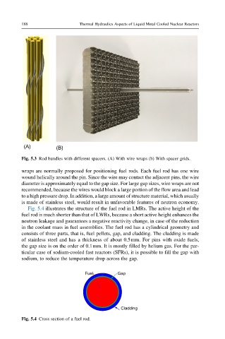
Fig. 5.4 illustrates the structure of the fuel rod in LMRs. The active height of the
fuel rod is much shorter than that of LWRs, because a short active height enhances the
neutron leakage and guarantees a negative reactivity change, in case of the reduction
in the coolant mass in fuel assemblies. The fuel rod has a cylindrical geometry and
consists of three parts, that is, fuel pellets, gap, and cladding. The cladding is made
of stainless steel and has a thickness of about 0.5mm. For pins with oxide fuels,
the gap size is on the order of 0.1mm. It is mostly filled by helium gas. For the par-
ticular case of sodium-cooled fast reactors (SFRs), it is possible to fill the gap with
sodium, to reduce the temperature drop across the gap.
Fuel Gap
Cladding
Fig. 5.4 Cross section of a fuel rod.