
Page 383 - Thermal Hydraulics Aspects of Liquid Metal Cooled Nuclear Reactors
P. 383
346 Thermal Hydraulics Aspects of Liquid Metal Cooled Nuclear Reactors
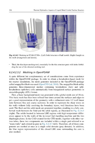
Fig. 6.2.4.2 Meshing in STAR-CCM+. (Left) Solid structure of half model. (Right) Insight on
the mesh arrangement and density.
l Third, the thin-layer meshing tool, essentially for the thin structure parts with holes forbid-
ding the use of the directed meshing tool.
6.2.4.2.3.2 Meshing in OpenFOAM
A quite different but complementary set of considerations come from experience
within the OpenFOAM package. In order to obtain a hexahedron-based mesh for
the reactor simulations, the mesh generator included in the OpenFOAM package
called snappyHexMesh was used (OpenCFD Ltd, 2018). The snappyHexMesh utility
generates three-dimensional meshes containing hexahedrons (hex) and split-
hexahedrons (split-hex) cells automatically from triangulated surface geometries in
stereolithography (STL) format.
First, a basic background mesh was generated with a global mesh size of 30cm.
This basic mesh has then been refined four times around the surfaces and edges to
get a good representation of the geometry with a refinement ratio 1:2 (cell linear
ratio between fine and coarse sections). In order to represent the shear stress on
the walls without fully resolving the boundary layers, wall functions have been
used. The fluid and the solid mesh are generated together, resulting in a fully con-
formal mesh between the fluid and the solid regions, as illustrated in Fig. 6.2.4.3
(right). The solids located in between LBE regions with high temperature differ-
ences appear to be the walls of the in-vessel fuel-handling machine and the two
diaphragm plates. In the CAD created for the CFD model, together with other var-
ious tubes, these two components are included within a single part referred to as
“main walls” and colored in gray in Fig. 6.2.4.3 (left). Therefore, all of these com-
ponents are meshed at once as a single solid domain (gray domain). In addition,
the blueregionrepresentativeofthe closed LBEzonesurrounding thecoreis
also meshed.