
Page 386 - Thermal Hydraulics Aspects of Liquid Metal Cooled Nuclear Reactors
P. 386
(U)RANS pool thermal hydraulics 349
time, mainly because the thermal equilibrium is very long to establish. The simulation
has to be accelerated; otherwise, its cost becomes prohibitive. It is thus compulsory to
increase the time step quite above the strict observance of the CFL constraint. The
consequence is that the LBE inventory is no more strictly conserved in time and that
the free surfaces show a smearing tendency. Countermeasures have to be taken:
l To maintain the LBE inventory almost constant in time, an LBE source term is carefully
defined and localized in order to reduce the mass error by adding or removing some LBE
in a “quiet” region. For this purpose, the LBE total mass must obviously be constantly
monitored.
l To counteract the interface smearing, a similar sink term for the cover gas is defined in order
to remove the cover gas from where it should not lay, that is, in the LBE bulk. This is simply
realized by making the term proportional to both volume fractions. In both cases, care must
be taken to add a corresponding source in the energy equation.
6.2.4.2.7 Geometrical macroscopic simplifications
The general constraints explained at the beginning collide with the specific interest,
objectives, and priorities of the modelers. Thus, while staying globally at the same
level of required computational power, different choices were made by both modelers.
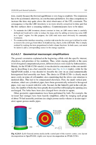
Mainly, for the STAR-CCM+ model, it was decided to concentrate on the core model-
ing by describing it on a fuel assembly basis (see Fig. 6.2.4.4 (right)), while for the
OpenFOAM model, it was decided to describe the core on an axial-symmetrically
homogenized fuel assembly raw basis. The choice in STAR-CCM+ is clearly much
more costly in terms of cell number, also considering that the above core structure is
modeled alike. This had to be compensated elsewhere. First, the small vertical pen-
etrations, which are cylindrical pipes, have been geometrically reduced to hexagonal
pipes, very easy to mesh with few cells. Second, for the butterfly grid in the cold ple-
num, the number of holes has been greatly decreased but still keeping the opening area
unchanged. The holes have been also changed from circular to square.
Other geometric approximations have been performed by both. For example, the
in-vessel fuel storages have been heavily simplified, either by merging each group
of about 70 fuel assembly positions in a single porous media volume or in nine equiv-
alent square porous media pipes.
CSP
Outer dummies
Inner dummies
Inner & outer FA
IPS+SR+CR
Core
Y
Z Z
X CRS X Y ΔP = f m •
Fig. 6.2.4.4 (Left) General porous media in the central part of the reactor: center, core layout
decomposition in OpenFOAM; (right) core layout decomposition in STAR-CCM+.