
Page 391 - Thermal Hydraulics Aspects of Liquid Metal Cooled Nuclear Reactors
P. 391
354 Thermal Hydraulics Aspects of Liquid Metal Cooled Nuclear Reactors
2% both in the core and between the cold plenum and hot plenum. This validates the
porous media approach applied.
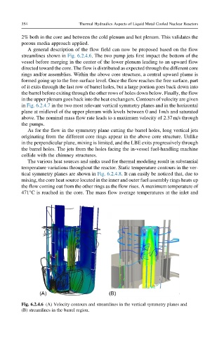
A general description of the flow field can now be proposed based on the flow
streamlines shown in Fig. 6.2.4.6. The two pump jets first impact the bottom of the
vessel before merging in the center of the lower plenum leading to an upward flow
directed toward the core. The flow is distributed as expected through the different core
rings and/or assemblies. Within the above core structure, a central upward plume is
formed going up to the free-surface level. Once the flow reaches the free surface, part
of it exits through the last row of barrel holes, but a large portion goes back down into
the barrel before exiting through the other rows of holes down below. Finally, the flow
in the upper plenum goes back into the heat exchangers. Contours of velocity are given
in Fig. 6.2.4.7 in the two most relevant vertical symmetry planes and in the horizontal
plane at midlevel of the upper plenum with levels between 0 and 1m/s and saturated
above. The nominal mass flow rate leads to a maximum velocity of 2.37m/s through
the pumps.
As for the flow in the symmetry plane cutting the barrel holes, long vertical jets
originating from the different core rings appear in the above core structure. Unlike
in the perpendicular plane, mixing is limited, and the LBE exits progressively through
the barrel holes. The jets from the holes facing the in-vessel fuel-handling machine
collide with the chimney structures.
The various heat sources and sinks used for thermal modeling result in substantial
temperature variations throughout the reactor. Static temperature contours in the ver-
tical symmetry planes are shown in Fig. 6.2.4.8. It can easily be noticed that, due to
mixing, the core heat source located in the inner and outer fuel assembly rings heats up
the flow coming out from the other rings as the flow rises. A maximum temperature of
471°C is reached in the core. The mass flow average temperatures at the inlet and
Fig. 6.2.4.6 (A) Velocity contours and streamlines in the vertical symmetry planes and
(B) streamlines in the barrel region.