
Page 389 - Thermal Hydraulics Aspects of Liquid Metal Cooled Nuclear Reactors
P. 389
352 Thermal Hydraulics Aspects of Liquid Metal Cooled Nuclear Reactors
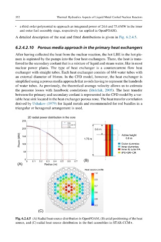
a third-order polynomial to approach an integrated power of 24.6 and 75.4MW in the inner
l
and outer fuel assembly rings, respectively (as applied in OpenFOAM).
A detailed description of the real and fitted distributions is given in Fig. 6.2.4.5.
6.2.4.2.10 Porous media approach in the primary heat exchangers
After having collected the heat from the nuclear reaction, the hot LBE in the hot ple-
num is aspirated by the pumps into the four heat exchangers. There, the heat is trans-
ferred to the secondary coolant that is a mixture of liquid and steam water, like in most
nuclear power plants. The type of heat exchanger is a countercurrent flow heat
exchanger with straight tubes. Each heat exchanger consists of 684 water tubes with
an external diameter of 16mm. In the CFD model, however, the heat exchanger is
simplified using a porous media approach that avoids having to represent the hundreds
of water tubes. As previously, the theoretical average velocity allows us to estimate
the pressure losses with handbook correlations (Idelchik, 2005). The heat transfer
between the primary and secondary coolant is represented in the CFD model by a var-
iable heat sink located in the heat exchanger porous zone. The heat transfer correlation
derived by Ushakov (1979) for liquid metals and recommended for rod bundles in a
triangular or hexagonal arrangement is used.
2D radial power distribution in the core
250
200 0.6 m
Power (MW) 150 1.75 m Outer dummies
Active height
0.6 m
100
Inner dummies
Inner & outer FA
50
IPS+SR+CR
0
0 0.1 0.2 0.3 0.4 0.5 0.6 0.7 (B)
(A) Radius (m)
Heat source profile
1.0
0.9
0.7
0.6
0.5
0.3
(C)
Fig. 6.2.4.5 (A) Radial heat source distribution in OpenFOAM, (B) axial positioning of the heat
source, and (C) radial heat source distribution in the fuel assemblies in STAR-CCM+.