
Page 393 - Thermal Hydraulics Aspects of Liquid Metal Cooled Nuclear Reactors
P. 393
356 Thermal Hydraulics Aspects of Liquid Metal Cooled Nuclear Reactors
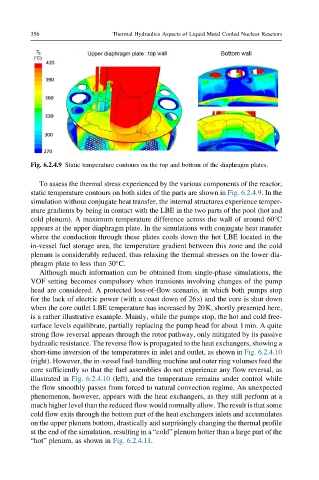
Fig. 6.2.4.9 Static temperature contours on the top and bottom of the diaphragm plates.
To assess the thermal stress experienced by the various components of the reactor,
static temperature contours on both sides of the parts are shown in Fig. 6.2.4.9. In the
simulation without conjugate heat transfer, the internal structures experience temper-
ature gradients by being in contact with the LBE in the two parts of the pool (hot and
cold plenum). A maximum temperature difference across the wall of around 60°C
appears at the upper diaphragm plate. In the simulations with conjugate heat transfer
where the conduction through these plates cools down the hot LBE located in the
in-vessel fuel storage area, the temperature gradient between this zone and the cold
plenum is considerably reduced, thus relaxing the thermal stresses on the lower dia-
phragm plate to less than 30°C.
Although much information can be obtained from single-phase simulations, the
VOF setting becomes compulsory when transients involving changes of the pump
head are considered. A protected loss-of-flow scenario, in which both pumps stop
for the lack of electric power (with a coast down of 26s) and the core is shut down
when the core outlet LBE temperature has increased by 20K, shortly presented here,
is a rather illustrative example. Mainly, while the pumps stop, the hot and cold free-
surface levels equilibrate, partially replacing the pump head for about 1min. A quite
strong flow reversal appears through the rotor pathway, only mitigated by its passive
hydraulic resistance. The reverse flow is propagated to the heat exchangers, showing a
short-time inversion of the temperatures in inlet and outlet, as shown in Fig. 6.2.4.10
(right). However, the in-vessel fuel-handling machine and outer ring volumes feed the
core sufficiently so that the fuel assemblies do not experience any flow reversal, as
illustrated in Fig. 6.2.4.10 (left), and the temperature remains under control while
the flow smoothly passes from forced to natural convection regime. An unexpected
phenomenon, however, appears with the heat exchangers, as they still perform at a
much higher level than the reduced flow would normally allow. The result is that some
cold flow exits through the bottom part of the heat exchangers inlets and accumulates
on the upper plenum bottom, drastically and surprisingly changing the thermal profile
at the end of the simulation, resulting in a “cold” plenum hotter than a large part of the
“hot” plenum, as shown in Fig. 6.2.4.11.