
Page 394 - Thermal Hydraulics Aspects of Liquid Metal Cooled Nuclear Reactors
P. 394
(U)RANS pool thermal hydraulics 357
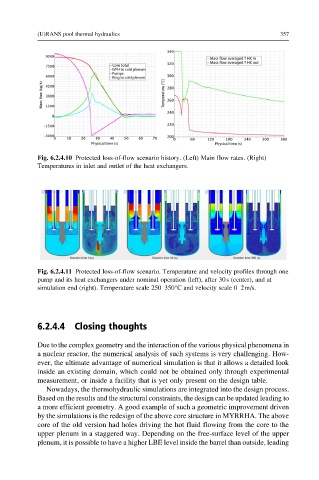
Fig. 6.2.4.10 Protected loss-of-flow scenario history. (Left) Main flow rates. (Right)
Temperatures in inlet and outlet of the heat exchangers.
Fig. 6.2.4.11 Protected loss-of-flow scenario. Temperature and velocity profiles through one
pump and its heat exchangers under nominal operation (left), after 30s (center), and at
simulation end (right). Temperature scale 250–350°C and velocity scale 0–2m/s.
6.2.4.4 Closing thoughts
Due to the complex geometry and the interaction of the various physical phenomena in
a nuclear reactor, the numerical analysis of such systems is very challenging. How-
ever, the ultimate advantage of numerical simulation is that it allows a detailed look
inside an existing domain, which could not be obtained only through experimental
measurement, or inside a facility that is yet only present on the design table.
Nowadays, the thermohydraulic simulations are integrated into the design process.
Based on the results and the structural constraints, the design can be updated leading to
a more efficient geometry. A good example of such a geometric improvement driven
by the simulations is the redesign of the above core structure in MYRRHA. The above
core of the old version had holes driving the hot fluid flowing from the core to the
upper plenum in a staggered way. Depending on the free-surface level of the upper
plenum, it is possible to have a higher LBE level inside the barrel than outside, leading