
Page 392 - Thermal Hydraulics Aspects of Liquid Metal Cooled Nuclear Reactors
P. 392
(U)RANS pool thermal hydraulics 355
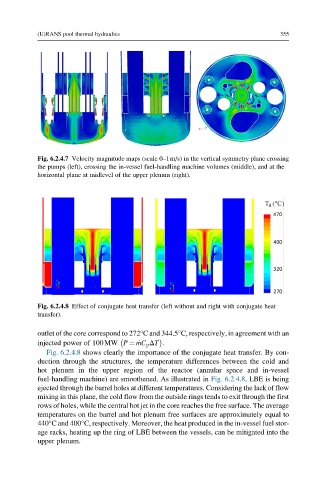
Fig. 6.2.4.7 Velocity magnitude maps (scale 0–1m/s) in the vertical symmetry plane crossing
the pumps (left), crossing the in-vessel fuel-handling machine volumes (middle), and at the
horizontal plane at midlevel of the upper plenum (right).
Fig. 6.2.4.8 Effect of conjugate heat transfer (left without and right with conjugate heat
transfer).
outlet of the core correspond to 272°C and 344.5°C, respectively, in agreement with an
injected power of 100MW P ¼ _ mC p ΔT .
Fig. 6.2.4.8 shows clearly the importance of the conjugate heat transfer. By con-
duction through the structures, the temperature differences between the cold and
hot plenum in the upper region of the reactor (annular space and in-vessel
fuel-handling machine) are smoothened. As illustrated in Fig. 6.2.4.8, LBE is being
ejected through the barrel holes at different temperatures. Considering the lack of flow
mixing in this plane, the cold flow from the outside rings tends to exit through the first
rows of holes, while the central hot jet in the core reaches the free surface. The average
temperatures on the barrel and hot plenum free surfaces are approximately equal to
440°C and 400°C, respectively. Moreover, the heat produced in the in-vessel fuel stor-
age racks, heating up the ring of LBE between the vessels, can be mitigated into the
upper plenum.