
Page 317 - Bird R.B. Transport phenomena
P. 317
§10.5 Heat Conduction with a Chemical Heat Source 301
Insulated Inert Catalyst Inert
walb particles particles ~*" particles
Zone I - Zone II Zone III -
2 = 0 z = L
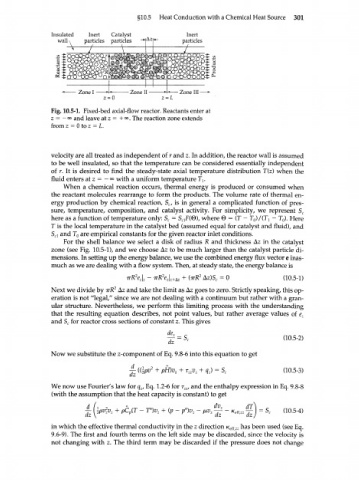
Fig. 10.5-1. Fixed-bed axial-flow reactor. Reactants enter at
z = - oo and leave at z = + <». The reaction zone extends
from z = 0 to z = L.
velocity are all treated as independent of r and z. In addition, the reactor wall is assumed
to be well insulated, so that the temperature can be considered essentially independent
of r. It is desired to find the steady-state axial temperature distribution T(z) when the
fluid enters at z = — oo with a uniform temperature T v
When a chemical reaction occurs, thermal energy is produced or consumed when
the reactant molecules rearrange to form the products. The volume rate of thermal en-
ergy production by chemical reaction, S , is in general a complicated function of pres-
c
sure, temperature, composition, and catalyst activity. For simplicity, we represent S c
here as a function of temperature only: S c = S^Fi®), where © = (T — Т )/(Т г — T ). Here
o
0
T is the local temperature in the catalyst bed (assumed equal for catalyst and fluid), and
S cl and T are empirical constants for the given reactor inlet conditions.
o
For the shell balance we select a disk of radius R and thickness Az in the catalyst
zone (see Fig. 10.5-1), and we choose Az to be much larger than the catalyst particle di-
mensions. In setting up the energy balance, we use the combined energy flux vector e inas-
much as we are dealing with a flow system. Then, at steady state, the energy balance is
2 2 (10.5-1)
irR e z \ z - (TTR AZ)S C = 0
Next we divide by irR 2 Az and take the limit as Az goes to zero. Strictly speaking, this op-
eration is not "legal," since we are not dealing with a continuum but rather with a gran-
ular structure. Nevertheless, we perform this limiting process with the understanding
that the resulting equation describes, not point values, but rather average values of e
z
and S for reactor cross sections of constant z. This gives
c
(10.5-2)
dz~ bc
Now we substitute the z-component of Eq. 9.8-6 into this equation to get
A, • + pH)v + r v + q ) = S (10.5-3)
2
dz z zz z z c
We now use Fourier's law for q , Eq. 1.2-6 for r , and the enthalpy expression in Eq. 9.8-8
2Z
z
(with the assumption that the heat capacity is constant) to get
= S (10.5-4)
dz r dz dz c
in which the effective thermal conductivity in the z direction /c eff/22 has been used (see Eq.
9.6-9). The first and fourth terms on the left side may be discarded, since the velocity is
not changing with z. The third term may be discarded if the pressure does not change