
Page 443 - Bird R.B. Transport phenomena
P. 443
§14.1 Definitions of Heat Transfer Coefficients 425
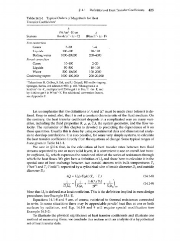
Table 14.1-1 Typical Orders of Magnitude for Heat
Transfer Coefficients"
h
(W/m 2 • K) or h
2
System (kcal/m • hr • C) (Btu/ft 2 • hr • F)
Free convection
Gases 3-20 1-4
Liquids 100-600 20-120
Boiling water 1000-20,000 200-4000
Forced convection
Gases 10-100 2-20
Liquids 50-500 10-100
Water 500-10,000 100-2000
Condensing vapors 1000-100,000 200-20,000
0 Taken from H. Grober, S. Erk, and U. Grigull, Warmeiibertragung,
Springer, Berlin, 3rd edition (1955), p. 158. When given h in
2
2
kcal/m • hr • C, multiply by 0.204 to get h in Btu/ft • hr • F, and
2
by 1.162 to get h in W/m • K. For additional conversion factors,
see Appendix F.
Let us emphasize that the definitions of A and AT must be made clear before h is de-
fined. Keep in mind, also, that h is not a constant characteristic of the fluid medium. On
the contrary, the heat transfer coefficient depends in a complicated way on many vari-
ables, including the fluid properties (к, д, р, C ), the system geometry, and the flow ve-
p
locity. The remainder of this chapter is devoted to predicting the dependence of h on
these quantities. Usually this is done by using experimental data and dimensional analy-
sis to develop correlations. It is also possible, for some very simple systems, to calculate
the heat transfer coefficient directly from the equations of change. Some typical ranges of
h are given in Table 14.1-1.
We saw in §10.6 that, in the calculation of heat transfer rates between two fluid
streams separated by one or more solid layers, it is convenient to use an overall heat trans-
fer coefficient, U , which expresses the combined effect of the series of resistances through
o
which the heat flows. We give here a definition of U o and show how to calculate it in the
special case of heat exchange between two coaxial streams with bulk temperatures T h
("hot") and T ("cold"), separated by a cylindrical tube of inside diameter D and outside
c
o
diameter D^
dQ = U (jrD dz)(T h - T ) (14.1-8)
o
c
Q
• + • (14.1-9)
W 2k m loc
o
Note that U o is defined as a local coefficient. This is the definition implied in most design
procedures (see Example 15.4-1).
Equations 14.1-8 and 9 are, of course, restricted to thermal resistances connected
in series. In some situations there may be appreciable parallel heat flux at one or both
surfaces by radiation, and Eqs. 14.1-8 and 9 will require special modification (see
Example 16.5-2).
To illustrate the physical significance of heat transfer coefficients and illustrate one
method of measuring them, we conclude this section with an analysis of a hypothetical
set of heat transfer data.