Page 457 - Bird R.B. Transport phenomena
P. 457

§14.3  Heat Transfer  Coefficients  for  Forced Convection in Tubes  437

                               Note also that Fig. 14.3-2 somewhat resembles  the friction-factor  plot in Fig. 6.2-2, al-
                           though  the  physical  situation  is  quite  different.  In  the  highly  turbulent  range  (Re  >
                           10,000)  the  heat  transfer  ordinate  agrees  approximately  with  //2  for  the  long  smooth
                                                                                  3
                           pipes under consideration. This was  first pointed out by Colburn,  who proposed the  fol-
                           lowing  empirical analogy  for  long, smooth tubes:
                                                     torn  *  \f    >  10,0001                (14.3-18)
                           in which
                                                   Nu                              2/3
                                                     ln                                       (14.3-19)
                                                  RePr  1/3  (pv)C  '     wC
                                                               p            n
                           where  S is the area  of  the tube cross  section, w  is the mass  rate of flow through the tube,
                           and//2  is obtainable from  Fig. 6.2-2 using  Re =  DW/SJJL = 4W/TTDIJL. Clearly the analogy
                           of  Eq. 14.3-18 is  not valid  below  Re  =  10,000.  For rough tubes with  fully  developed  tur-
                           bulent  flow  the analogy  breaks  down  completely, because / is  affected  more by  rough-
                           ness than j  is.
                                    H
                               One additional remark about the use  of  Fig.  14.3-2 has to do with  the application to
                           conduits  of  noncircular cross  section.  For highly turbulent flow, one  may  use  the mean
                           hydraulic  radius  of  Eq.  6.2-16.  To apply  that  empiricism,  D is  replaced  by  AR h  every-
                           where in the Reynolds and Nusselt numbers.


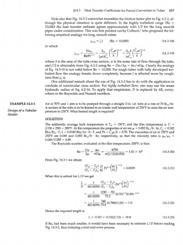
       EXAMPLE   14.3-1    Air  at  70°F and 1 atm is to be pumped through a straight  2-in. i.d. tube at a rate of  70 lb /hr.
                                                                                                  w
                           A section of the tube is to be heated to an inside wall temperature of 250°F to raise the air tem-
      Design of  a  Tubular  perature to 230°F. What  heated length is required?
      Heater
                           SOLUTION
                           The  arithmetic average  bulk  temperature is  T ba  =  150°F, and  the  film  temperature is  7y =
                           |(150 + 250) = 200°F. At this temperature the properties of air are  /x, = 0.052 lb /ft  • hr, C p  = 0.242
                                                                                       m
                           Btu/lb  • F, fc = 0.0180 Btu/hr •  ft • F, and Pr = С /л/к = 0.70. The viscosities  of air at 150°F and
                                                                     р
                                 m
                           250°F  are  0.049  and  0.055  lb /ft  - hr,  respectively,  so  that  the  viscosity  ratio  is  \x l ^  =
                                                   w
                                                                                                b
                           0.049/0.055 = 0.89.
                               The Reynolds number, evaluated  at the film  temperature, 200°F, is then
                                                  Dw    4w       4(70)    =  1.02  X 10 4      (14.3-20)
                                                              TT(2/12)(0.052)
                           From Fig. 14.3-1 we obtain
                                                      ~  T )
                                                         M      2 / 3
                                                           4 f P r  ^   =0.0039                (14.3-21)
                           When  this is solved  for L/D we  get
                                                       1    (Tt,o -  Гм)  / и Л  0 1 4
                                                       1   К1 Ь2  L  b \ ) p  2/3 Mb
                                                D
                                                    4(0.0039)  (T  -  ГД„  V^°/
                                                             o
                                                       1   (230  -  70)  (0.70) (0.89Г 014
                                                                         2/3
                                                    4(0.0039)  72.2
                                                       1    160
                                                    4(0.0039)  72.8  (0.788X1.02)  = 113       (14.3-22)
                           Hence the required length is
                                                    L = 113D = (113X2/12)  = 19  ft            (14.3-23)

                           If Re  had been much smaller, it would  have been necessary  to estimate L/D before  reading
                               b
                           Fig. 14.3-2, thus initiating a trial-and-error process.
   452   453   454   455   456   457   458   459   460   461   462