
Page 499 - Bird R.B. Transport phenomena
P. 499
Problems 479
15B.4. The Mach number in the mixing of two fluid streams.
(a) Show that when the radicand in Eq. 15.3-13 is zero, the Mach number of the final stream is
unity. Note that the Mach number, Ma, which is the ratio of the local fluid velocity to the ve-
locity of sound at the local conditions, may be written for an ideal gas asv/v s = v/\/yRT/M
(see Problem 11C.1).
(b) Show how the results of Example 15.3-2 may be used to predict the behavior of a gas
passing through a sudden enlargement of duct cross section.
15B.5. Limiting discharge rates for Venturi meters.
(a) Starting with Eq. 15.5-34 (for adiahatic flow), show that as the throat pressure in a Venturi
meter is reduced, the mass rate of flow reaches a maximum when the ratio r = p 2/p\ of throat
pressure to entrance pressure is defined by the expression
7 + 1
(15B.5-1)
(b) Show that for Si » S o the mass flow rate under these limiting conditions is
W[_
w = C dpiS Oy (15B.5-2)
(d) Obtain results analogous to Eqs. 15B.5-1 and 2 for isothermal flow.
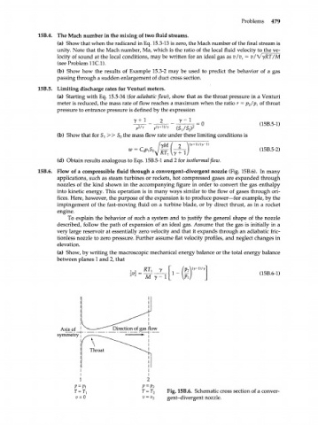
15B.6. Flow of a compressible fluid through a convergent-divergent nozzle (Fig. 15B.6). In many
applications, such as steam turbines or rockets, hot compressed gases are expanded through
nozzles of the kind shown in the accompanying figure in order to convert the gas enthalpy
into kinetic energy. This operation is in many ways similar to the flow of gases through ori-
fices. Here, however, the purpose of the expansion is to produce power—for example, by the
impingement of the fast-moving fluid on a turbine blade, or by direct thrust, as in a rocket
engine.
To explain the behavior of such a system and to justify the general shape of the nozzle
described, follow the path of expansion of an ideal gas. Assume that the gas is initially in a
very large reservoir at essentially zero velocity and that it expands through an adiabatic fric-
tionless nozzle to zero pressure. Further assume flat velocity profiles, and neglect changes in
elevation.
(a) Show, by writing the macroscopic mechanical energy balance or the total energy balance
between planes 1 and 2, that
RT,
(15B.6-1)
M y-
Axis of
symmetry
Fig. 15B.6. Schematic cross section of a conver-
gent-divergent nozzle.