Page 502 - Bird R.B. Transport phenomena
P. 502

482   Chapter 15  Macroscopic Balances  for Nonisothermal Systems

                            (a)  By means  of  an energy  balance, show  that the slurry  temperature T(t) is  described  by  the
                            differential  equation

                                                  dT  _  UA
                                                                                               (15B.8-1)
                            The  variable  t is the time since the start  of heating.
                            (b)  Rewrite this differential  equation in terms  of the dimensionless  variables

                                                                                             (15B.8-2,3)
                                                                     T  -  T
                                                                     1  I  - 1  ОС
                            where
                                                            (UA/wC )T
                                                        T  =       p  5                        (15B.8-4)
                                                              (UA/wC )
                                                                    p
                            What  is the physical  significance  of  r, 0, and T ?
                                                                 x
                            (c)  Solve the dimensionless equation obtained in (b) for the initial condition that Г =  Г,- at f = 0.
                            (d)  Check the solution  to see that the differential  equation and initial condition are  satisfied.
                            How does  the system  behave  at large  time? Is this limiting behavior  in agreement with  your
                            intuition?
                            (e)  How is the temperature at infinite time affected  by the flow rate? Is this  reasonable?
                                     Г -  Г     Г
                            Answer: (с)  _  те  = exp
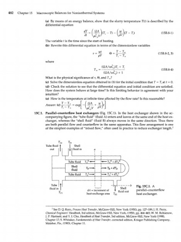
                     15С.1.  Parallel-counterflow  heat  exchangers  (Fig.  15C.1).  In the heat  exchanger  shown  in  the ac-
                            companying figure,  the "tube fluid"  (fluid  A) enters and leaves  at the same end  of the heat ex-
                            changer, whereas  the  "shell  fluid"  (fluid  B) always  moves  in the same  direction. Thus there
                            are both parallel flow and  counterflow  in the same apparatus. This flow arrangement is one
                            of the simplest  examples  of  "mixed flow," often  used  in practice to reduce exchanger  length. 2


                            Tube  fluid t  1  Shell
                              out           fluid in


                                         Tube fluid
                                           Shell
                                           fluid
                                         Tube fluid


                               Tube                                              Fig.lSC.l,  A
                              fluid in                                 Shell
                                                    dA = increment of  fluid out  parallel-counterflow
                                                    heat-exchange  area  l B2    heat  exchanger.


                               2  See D. Q. Kern, Process Heat Transfer, McGraw-Hill, New York  (1950), pp. 127-189; J. H. Perry,
                            Chemical Engineers' Handbook, 3rd edition, McGraw-Hill, New York, (1950), pp. 464-465; W.  M. Rohsenow,
                            J. P. Hartnett, and  Y.  I. Cho, Handbook of Heat  Transfer, 3rd edition, McGraw-Hill, New York  (1998),
                            Chapter  17; S. Whitaker,  Fundamentals  of Heat Transfer, corrected edition, Krieger  Publishing  Company,
                            Malabar, Fla., (1983), Chapter 11.
   497   498   499   500   501   502   503   504   505   506   507