
Page 221 - Trenchless Technology Piping Installation and Inspection
P. 221
Pr oject Considerations for Horizontal Dir ectional Drilling 185
time, the product pipe is connected to the end of the drilling rod by a
swivel and pulled back through the enlarged pilot borehole. How-
ever, for large-diameter pipes, a separate (intermediate) phase
comprising several passes of backreaming (or “prereaming”) may be
necessary to enlarge the borehole to the desired size. In this case, the
pullback operation is performed simultaneously with the final back-
reaming operation. The pilot borehole is drilled with a surface-
launched rig with an inclined carriage, typically adjusted at an angle
of 8° to 20° with the ground surface. Figure 5.1 illustrates a generic
HDD installation.
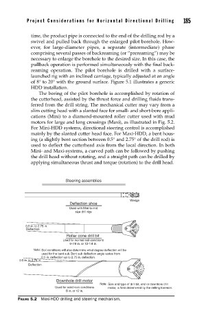
The boring of the pilot borehole is accomplished by rotation of
the cutterhead, assisted by the thrust force and drilling fluids trans-
ferred from the drill string. The mechanical cutter may vary from a
slim cutting head with a slanted face for small- and short-bore appli-
cations (Mini) to a diamond-mounted roller cutter used with mud
motors for large and long crossings (Maxi), as illustrated in Fig. 5.2.
For Mini-HDD systems, directional steering control is accomplished
mainly by the slanted cutter head face. For Maxi-HDD, a bent hous-
ing (a slightly bent section between 0.5° and 2.75° of the drill rod) is
used to deflect the cutterhead axis from the local direction. In both
Mini- and Maxi-systems, a curved path can be followed by pushing
the drill head without rotating, and a straight path can be drilled by
applying simultaneous thrust and torque (rotation) to the drill head.
Steering assemblies
Wedge
Deflection shoe
Used with Mini to mid
size drill rigs
0.5 in. to 2.75 in.
Deflection
Roller cone drill bit
Used for normal soil conditions
9-7/8 in. or 12-1/4 in.
Note: Soil conditions will also determine what degree deflection will be
used for the bent sub. Bent sub deflection angle varies from
0.5 in. deflection up to 2.75 in. deflection.
0.5 in. to 2.75 in.
Deflection
Downhole drill motor
Note: Size and type of drill bit, and or downhole drill
Used for solid rock conditions motor, is field determined by the drilling foreman.
B in. or 12 in.
FIGURE 5.2 Maxi-HDD drilling and steering mechanism.