
Page 232 - Trenchless Technology Piping Installation and Inspection
P. 232
196 Cha pte r F i v e
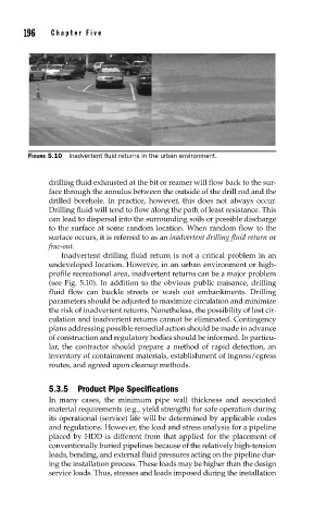
FIGURE 5.10 Inadvertent fl uid returns in the urban environment.
drilling fluid exhausted at the bit or reamer will flow back to the sur-
face through the annulus between the outside of the drill rod and the
drilled borehole. In practice, however, this does not always occur.
Drilling fluid will tend to flow along the path of least resistance. This
can lead to dispersal into the surrounding soils or possible discharge
to the surface at some random location. When random flow to the
surface occurs, it is referred to as an inadvertent drilling fluid return or
frac-out.
Inadvertent drilling fluid return is not a critical problem in an
undeveloped location. However, in an urban environment or high-
profile recreational area, inadvertent returns can be a major problem
(see Fig. 5.10). In addition to the obvious public nuisance, drilling
fluid flow can buckle streets or wash out embankments. Drilling
parameters should be adjusted to maximize circulation and minimize
the risk of inadvertent returns. Nonetheless, the possibility of lost cir-
culation and inadvertent returns cannot be eliminated. Contingency
plans addressing possible remedial action should be made in advance
of construction and regulatory bodies should be informed. In particu-
lar, the contractor should prepare a method of rapid detection, an
inventory of containment materials, establishment of ingress/egress
routes, and agreed upon cleanup methods.
5.3.5 Product Pipe Specifications
In many cases, the minimum pipe wall thickness and associated
material requirements (e.g., yield strength) for safe operation during
its operational (service) life will be determined by applicable codes
and regulations. However, the load and stress analysis for a pipeline
placed by HDD is different from that applied for the placement of
conventionally buried pipelines because of the relatively high-tension
loads, bending, and external fluid pressures acting on the pipeline dur-
ing the installation process. These loads may be higher than the design
service loads. Thus, stresses and loads imposed during the installation