
Page 228 - Trenchless Technology Piping Installation and Inspection
P. 228
192 Cha pte r F i v e
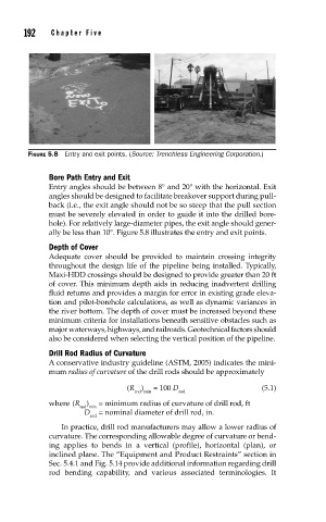
FIGURE 5.8 Entry and exit points. (Source: Trenchless Engineering Corporation.)
Bore Path Entry and Exit
Entry angles should be between 8° and 20° with the horizontal. Exit
angles should be designed to facilitate breakover support during pull-
back (i.e., the exit angle should not be so steep that the pull section
must be severely elevated in order to guide it into the drilled bore-
hole). For relatively large-diameter pipes, the exit angle should gener-
ally be less than 10°. Figure 5.8 illustrates the entry and exit points.
Depth of Cover
Adequate cover should be provided to maintain crossing integrity
throughout the design life of the pipeline being installed. Typically,
Maxi-HDD crossings should be designed to provide greater than 20 ft
of cover. This minimum depth aids in reducing inadvertent drilling
fluid returns and provides a margin for error in existing grade eleva-
tion and pilot-borehole calculations, as well as dynamic variances in
the river bottom. The depth of cover must be increased beyond these
minimum criteria for installations beneath sensitive obstacles such as
major waterways, highways, and railroads. Geotechnical factors should
also be considered when selecting the vertical position of the pipeline.
Drill Rod Radius of Curvature
A conservative industry guideline (ASTM, 2005) indicates the mini-
mum radius of curvature of the drill rods should be approximately
(R ) = 100 D (5.1)
rod min rod
where (R ) = minimum radius of curvature of drill rod, ft
rod min
D = nominal diameter of drill rod, in.
rod
In practice, drill rod manufacturers may allow a lower radius of
curvature. The corresponding allowable degree of curvature or bend-
ing applies to bends in a vertical (profile), horizontal (plan), or
inclined plane. The “Equipment and Product Restraints” section in
Sec. 5.4.1 and Fig. 5.14 provide additional information regarding drill
rod bending capability, and various associated terminologies. It