
Page 330 - Trenchless Technology Piping Installation and Inspection
P. 330
Construction and Inspection for Cur ed-in-Place Pipe 289
In the case of vacuum impregnation, once the resin and catalyst
have been mixed, it is pumped into the fabric tube. Serial vacuum
impregnation involves placing a vacuum suction attachment at pre-
determined intervals, evacuating the tube of air, allowing the resin to
fill the evacuated liner area and patching the tube to seal the penetra-
tion of the vacuum device. Other impregnation techniques include
resin bath immersion or utilizing gravity for the resin/catalyst mix-
ture to fully impregnate the tube. Regardless of the method, total satu-
ration of the fabric tube is critical and mandatory. Most tube coatings are
transparent, which allows for a visual confirmation that the tube has
been thoroughly wet-out with no apparent visible dry spots existing.
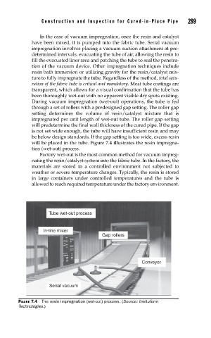
During vacuum impregnation (wet-out) operations, the tube is fed
through a set of rollers with a predesigned gap setting. The roller gap
setting determines the volume of resin/catalyst mixture that is
impregnated per unit length of wet-out tube. The roller gap setting
will predetermine the final wall thickness of the cured pipe. If the gap
is not set wide enough, the tube will have insufficient resin and may
be below design standards. If the gap setting is too wide, excess resin
will be placed in the tube. Figure 7.4 illustrates the resin impregna-
tion (wet-out) process.
Factory wet-out is the most common method for vacuum impreg-
nating the resin/catalyst system into the fabric tube. In the factory, the
materials are stored in a controlled environment not subjected to
weather or severe temperature changes. Typically, the resin is stored
in large containers under controlled temperatures and the tube is
allowed to reach required temperature under the factory environment.
Tube wet-out process
In-line mixer
Gap rollers
Conveyor
Serial vacuum
FIGURE 7.4 The resin impregnation (wet-out) process. (Source: Insituform
Technologies.)